Download

1 / 37
400 likes | 633 Views
Resistors. How can we intentionally change the amount of resistance in our circuit?. Which of the three parts of Ohm’s triangle do we have the most control over?. Resistance Voltage Current is a function of these two What if we want to control the current or alter the voltage?

E N D
Resistors How can we intentionally change the amount of resistance in our circuit?
Which of the three parts of Ohm’s triangle do we have the most control over? • Resistance • Voltage • Current is a function of these two • What if we want to control the current or alter the voltage? • Change the Resistance! • How do we do this?
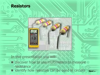
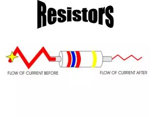
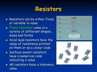
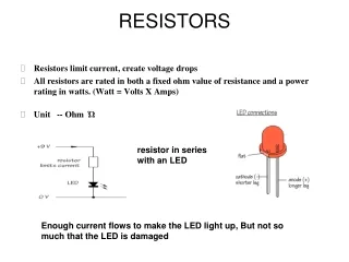
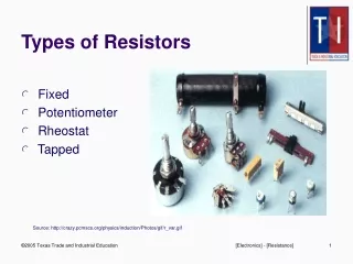
Basic Information • Resistor – A component that resists the flow of electric current, or blocks/slows down the flow. • Resistors are very small, so we use color bands painted on them to signify how many ohms (units of resistance) they have.
How to Read the Colors • Black 0 • Brown 1 • Red 2 • Orange 3 • Yellow 4 • Green 5 • Blue 6 • Violet 7 • Gray 8 • White 9 • The color band at the end is decoded as a number. • The middle color band is also decoded as a number. • The third band tells you how many zeroes to write after the first two numbers.
Resistors • The band to the left is red, so our first number is 2. • The second band from the left is violet so the next number is 7. • The third band is green so the amount of zeroes we add are 5. • This has 2,700,000 ohms of resistance. 2 – 7 – (0 0 0 0 0) 2,700,000 ohms
Take a look at that picture again, and notice the gold band all the way on the right. We don’t have a value for gold or silver because they mean different things. • Gold means it is give or take 5% away from the value. • Silver means it is give or take 10% away from the value.
Gold & Silver • The gold and silver bars are kind of like someone saying… • “Not quite sure if we are completely accurate, but it is within 5% (gold) or 10% (silver) of being right. • Gold is really good -> 5% • Silver is pretty good -> 10%
Let’s Try Some Out • Violet-Green-Red • Red-Orange-Black • Green-Gray-Yellow • 7500 ohms • 23ohms • 580,000 ohms
What if we add the band at the end? • Brown-Gray-Orange - Gold • 18,000 (give or take 5%) • 18,000 x .95 = 17,100 • 18,000 x 1.05 = 18,900 The range would be 17,100 – 18,900
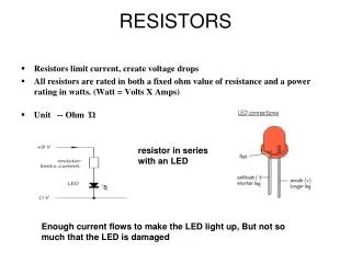
Some resistors conduct electricity- - some don’t have enough to light the lamp • Actually all resistors conduct electricity, but some do not conduct enough to light a lamp. • All resistors in a series with lamps make the lamp glow dimmer.
Each different resistor in series with a lamp makes it glow with a different brightness. Some resistors in parallel with lamps make the lamp dim a tiny bit; some resistors in parallel with lamps don’t affect the brightness of lamps. Some resistors get warm when they are in parallel with a lamp.
The resistor makes the lamps dimmer. How can you explain this observation?
What do you think is happening inside the resistor to cause the lamp to burn with reduced intensity?
Resistor Investigation (option 1) Find four resistors in your kit with colored bands. Set up the circuit pictured to the right. Put the resistors into the circuit one at a time and close the switch. Observe the intensity of the light from the bulb. List the resistors in order from brightest to dimmest light. Decode the color band and write the value of each resistor.
Resistors and lamp-brightness inquiry (2) • Different resistors seem to affect lamps in different ways. Work with your partner to find out if this is true. • Design an efficient system for testing the different resistors. • Draw a schematic to show your test circuit. • Conduct your investigation and gather data. • Organize your results in a way that is easy to understand.
Resistors and Lamp-Brightness Plan (3) Design an efficient system for testing the different resistors, one at a time, in series with a lamp. Test each resistor and observe the lamp’s brightness. Put the resistors in order from brightest light to dimmest light. Record the resistor information in your journal, using the color-band names for the resistors. Draw a schematic of your test circuit.
Lab Pages 7 and 9 in your lab notebook
Measuring Voltage 3/9/2011
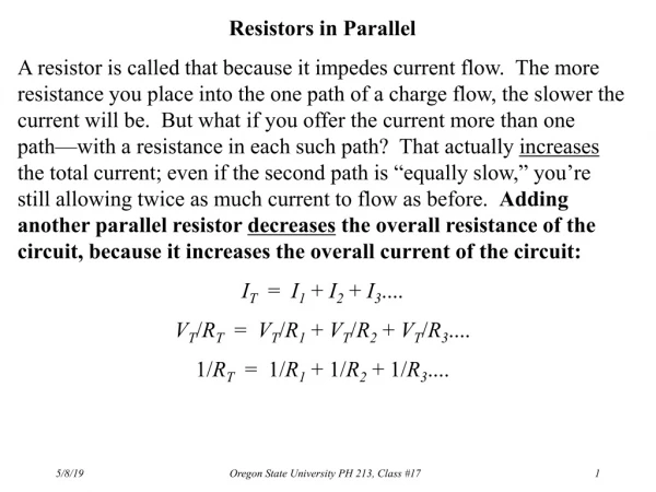
Electricity flows through circuits because it is pushed by a force is called voltage. We measure voltage by setting the multimeter to its voltmeter position touching the two meter probes to the two sides of a component. The amount of voltage used by that component is reported as voltage drop.
How to use a Voltmeter Turn the rotary switch three clicks counterclockwise to the 20-V Setting. The meter is now a voltmeter. At this setting the voltmeter can measure voltage between 0 and 20 V. Set up a circuit and close the switch. Voltage is always measured with current flowing through the circuit. Touch the two probes on the two sides of A component to measure its voltage drop. The red probe goes on the positive (+) side. Read the voltage drop across the component on the display.
Voltage Drop The difference in the amount of voltage on the two sides of a component is what the voltmeter measures. The voltmeter measures the amount of voltage “used” by a component. The amount of voltage used by a component is its voltage drop. We always refer to the voltmeter reading as a voltage drop.
How do you explain the voltage drop across a lamp in a circuit?
Voltage drop is like energy that gets used up Voltage drop is like the amount of push needed to get current through a component.
The Greater the resistance in series with a lamp, the dimmer the lamp glows.
***** Important ***** Add a resistor to your investigation. Use black/black/black - - or 0-Ω resistance How could you make a resistor with 0-Ω of resistance? (The copper wire)
Class Data Use the 0-Ω resistor data - - Lets compare our data as a class Cross off the highest and lowest values. Average all the values
Is there a pattern in the amount of voltage drop across the resistor?
Is there a pattern in the amount of voltage drop across the resistor? The greater the resistance the greater the voltage drop across the resistor.
Is there a pattern in the amount of voltage drop across the lamp?
Is there a pattern in the amount of voltage drop across the lamp? • The greater the resistance, the less the voltage drop across the lamp
How do these voltages-drop patterns relate to the size of the resistor in the circuit with the lamp?
How do these voltages-drop patterns relate to the size of the resistor in the circuit with the lamp? • As the resistance increases, the voltage across the resistor increases and the voltage across the lamp decreases.
Add up the lamp and resistor voltages for each resistor. Is there a pattern?
Add up the lamp and resistor voltages for each resistor. Is there a pattern? • The sum of the voltage drops in the circuit equals the available voltage across the terminals of the battery.
Lab Page 12 in your lab notebook