Download
1 / 44

E N D
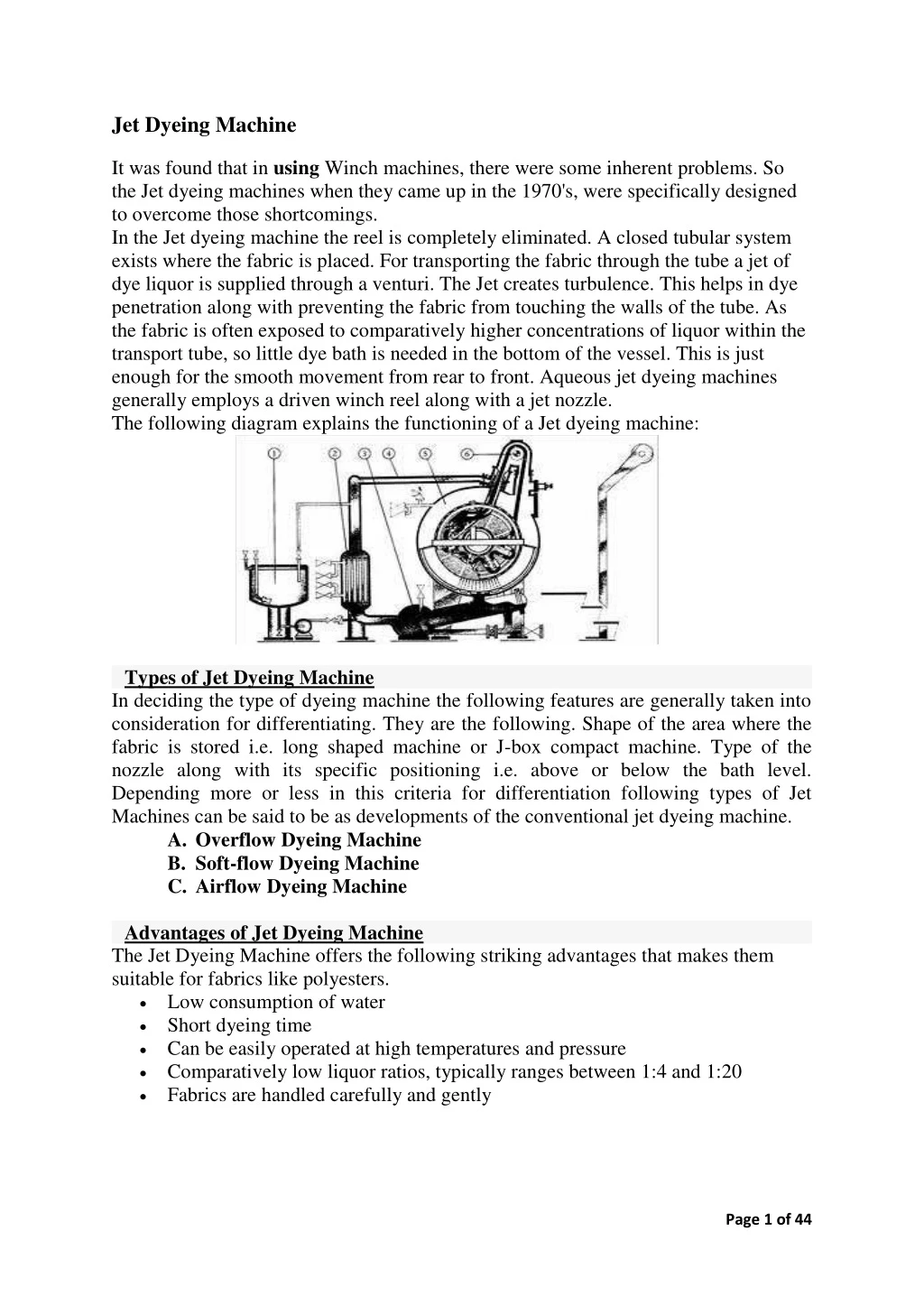
Jet Dyeing Machine It was found that in using Winch machines, there were some inherent problems. So the Jet dyeing machines when they came up in the 1970's, were specifically designed to overcome those shortcomings. In the Jet dyeing machine the reel is completely eliminated. A closed tubular system exists where the fabric is placed. For transporting the fabric through the tube a jet of dye liquor is supplied through a venturi. The Jet creates turbulence. This helps in dye penetration along with preventing the fabric from touching the walls of the tube. As the fabric is often exposed to comparatively higher concentrations of liquor within the transport tube, so little dye bath is needed in the bottom of the vessel. This is just enough for the smooth movement from rear to front. Aqueous jet dyeing machines generally employs a driven winch reel along with a jet nozzle. The following diagram explains the functioning of a Jet dyeing machine: Types of Jet Dyeing Machine In deciding the type of dyeing machine the following features are generally taken into consideration for differentiating. They are the following. Shape of the area where the fabric is stored i.e. long shaped machine or J-box compact machine. Type of the nozzle along with its specific positioning i.e. above or below the bath level. Depending more or less in this criteria for differentiation following types of Jet Machines can be said to be as developments of the conventional jet dyeing machine. A.Overflow Dyeing Machine B.Soft-flow Dyeing Machine C.Airflow Dyeing Machine Advantages of Jet Dyeing Machine The Jet Dyeing Machine offers the following striking advantages that makes them suitable for fabrics like polyesters. Low consumption of water Short dyeing time Can be easily operated at high temperatures and pressure Comparatively low liquor ratios, typically ranges between 1:4 and 1:20 Fabrics are handled carefully and gently Page 1 of 44
A.Overflow Dyeing Machine Overflows Dyeing Machines are designed for use in delicate knitted and woven fabrics that are made up of natural as well as synthetic fibers. They are also extensively used in the production of carpets. The main difference between jet and overflows machines is that in jet machines the fabric gets transported by a bath that flows at high speed through the nozzle, while in Overflow Dyeing Machine it is the gravitational force of the liquor overflow that is responsible for fabric transportation. Functioning of a Overflow Dyeing Machine A typical Overflow Dyeing Machine works like this. A winch that is not motor driven usually is located in the top side of the machine where the fabric is hanged. A longer length of textile is made to hang from the exit side of the winch as compared to the inlet side. By applying the force of gravitation the longer length of textile is pulled downward more strongly than the shorter one. Consequently the fabric is soaked in the bath without any sort of tension. The following diagram well illustrates the working process. Page 2 of 44
Some models of Overflow Jet Dyeing Machine 1.ASME-B HTHP Jet Overflow Dyeing Machine 2.ASME 500D Jet Overflow Dyeing Machine 3.ASME-D HTHP Jet Overflow Fabric Dyeing Machine 1. ASME-B HTHP Jet Overflow Dyeing Machine Place of Origin: Jiangsu China (Mainland) Brand Name: SUNTEX Model Number: ASME-B Material: SS316L Specifications ASME-B Jet Overflow Dyeing Machine is used for dyeing chemical fiber , synthetic woven and knitting fabric. ASME-B HTHP Jet Overflow Dyeing Machine is used for chemical fiber , synthetic woven and knitting fabric to be dyed and fore-and-after treatment in high temperature and high pressure . Range of fabric gram suitable : 60 -600 g /m 2 , for transmit knitting and woven fabrics . Page 3 of 44
Technical Parameters : SME-150B SME-250B Items SME-500B Form of the machine Horizontal tubular jet overflow single pipe 1:5---1:8 Horizontal tubular jet overflow single pipe 1:5---1:8 Horizontal tubular jet overflow single pipe Liquor Ratio 1:5---1:8 Max Fabric Capacity (kg ) 100-150 200-250 400-500 Max Working Temperature ( ) Max Working Pressure (Mpa ) 14 0 14 0 14 0 0.40Mpa 0.40Mpa 0.40Mpa Fabric Speed (m/min) 60-300 60-300 60-300 5 6 Heating Exchanging Area ( ) 12 Main Pump Power (KW ) 14.7 18.75 22.95 Page 4 of 44
2. ASME 500D Jet Overflow Dyeing Machine Place of Origin: Jiangsu China (Mainland) Brand Name: SUNTEX Model Number: ASME-D Material: stainless steal Specifications ASME 500D Jet Overflow Dyeing Machines. Each tube can run into two ropes at the same time. Big bend tube can save 10 % water. ASME 500D Jet Overflow Dyeing Machine is used for dyeing woven and knitted fabrics of cotton, polyester, and nylon and so on. This jet dyeing machine, ASME- 150 D , ASME-250 D, ASME-500 D , ASME -1000D ,four types . Special Design: Each tubes separates into two chambers (running into two ropes at the same time) Big bend tube can save 10 % water and space. ASME-500D Main Tech Data : Number of tubes (chambers) : 2/4 Max Capacity: 250 kg Liquor ratio: 1:6---1:10 Max working temperature : 140. Speed : Jet flow: 0-450 rpm Overflow: 0- 250 rpm Heating Speed: 35 min ( 20 ---140 ) Cooling Speed: 30 min (140 --- 60) Total motor power : 38.45 kw Overall Dimension : 6900x3100x2300 (economical size)   8090x3100x3080 (standard size) (01) ASME D series high temperature high speed double overflow dyeing machine uses the unique design of double purpose nozzle for overflow and jet. Page 5 of 44
(02) You only need to replace the nozzle; you can transform the water into that of soft pure overflow type (03) Water flow of low jet pressure and large pressure and high speed according to the classification of fabric. (04) Wide fabric application: Wide range of dyeing, including woven and knit fabric. Advantages of Overflow Dyeing Machine No evaporative losses- As the dyeing vessel is closed, there is no evaporative losses stemming from the dye bath. Further, depending on the situation the temperature may be raised to more than 1000oC. No build up of steam condensate in the dye bath- The latest technology implies that the dye bath gets heated by a heat transducer which is steam driven. This technology apart from being very efficient ensures that there is no build up of steam condensate in the dye bath. Low liquor ratios- Dyeing is conducted at relatively low liquor ratios, e.g. 10:1 and may be lesser resulting in substantial savings in water and energy. Excellent dye liquor contact- Excellent dye liquor contact with the fabric rope results in better and more improved level dyeing. Computer control- The machines are operated by computer and hence, operator error is eliminated. Page 6 of 44
B.Soft-flow Dyeing Machine In the soft flow dyeing machine water is used for keeping the fabric in circulation. The conceptional difference of this equipment from a conventional jets that operates with a hydraulic system is that the fabric rope is kept circulating during the whole processing cycle (right from loading to unloading). There is no stopping of liquor or fabric circulation for usual The principle working behind the technique is very unique. There is a system for fresh water to enter the vessel via a heat exchanger to a special interchange zone. At the same time the contaminated liquor is allowed channel out through a drain without any sort of contact with the fabric or for that matter the new bath in the machine. drain and fill steps. Key Features of Soft flow Dyeing Machine Significant savings in processing time. Savings in water that is around 50%. Excellent separation of different streams results in optimum heat recovery and a distinct possibility of further use or a dedicated treatment. Types of Soft Flow Dyeing Machine A few of the commercially popular brands along with their particular technical specifications are discussed here. The categories are not exhaustive as such 1.Multi Nozzle Softflow Dyeing Machine These textile machines are used with a purpose of dyeing Dye - 30 to 450 g./mt.sq. Fabrics (woven & knitted fabrics) with a Capacity 50 to 2000kgs. Understanding the need of the artificial fiber, it dyes a textile in a way that it retains its luster. EXCLUSIVE FEATURES Ultra low Liquor ratio - 1:1 (Wet Fabric) Dye - 30 to 450 g./mt.sq. Fabrics (woven & knitted fabrics). Number of very soft-flow nozzles & jet nozzles. No pilling effect. Work as a jet dyeing machine for polyester & blend fabrics. Work as a soft flow machine for cotton fabrics. Reduce pollution plant size. No colour inlet pump (optional) - Dozing pump High temp. up to 140° C. Capacity 50 to 2000kgs. Page 7 of 44
Multi - Nozzle Low/High temp. Dyeing technology work as a soft flow as well as jet dyeing machine. The main advantage of this development is to increase machine flexibility/ versatility to process all types of fabrics. In this new technical development, the nozzle 3 & 4 are big diameter and fix nozzle with individual flow control valve. The 1st main nozzle is adjustable. By increasing and decreasing the gap of nozzle, flow and pressure will be increase and decrease as per fabric quality demand. To run this machine as a soft flow machine, increase the gap that decrease the pressure and increase water flow, at that time all three nozzles are working as a soft flow and water flow control individually by control valve as per fabric quality demand. To run machine as a jet dying machine, decrease the gap of nozzle that increase the pressure and decrease the water flow. That time soft-nozzle control valve is close. Dimension Diagram Page 8 of 44
Specifications & Dimension are subject to change without any prior notice. Dimension (A) Mm / inch Dimension (B) Mm / inch Dimension (C) mm / inch 3150 / 124 3850 / 151 4550 / 209 5250 / 206 6000 / 236 6700 / 263 Model Capacity (Kgs.) (Chamber)50 2 3 4 5 6 7 300 450 600 750 900 1050 4650 / 183 4650 / 183 4650 / 183 4650 / 183 4650 / 183 4650 / 183 3350 / 131 3350 / 131 3350 / 131 3350 / 131 3350 / 131 3350 / 131 2.High Temperature High Pressure Softflow Dyeing Machine HT.HP soft flow dyeing machines are multi type dyeing machines. These textile machines are used with a purpose of dyeing a larger division of cloth. It dyes cotton, hosiery and crape cloth material. Understanding the need of the cloth, it dyes a textile in a way that it retains its luster for long. Exclusive Features: Lowest liquor ratio. Reduce colour & chemicals. Reduce steam consumption. Reduce electricity. Tangle free operation. Online washing system. Inner flow dyeing system. No rope marks, no pilling effect, no hairiness. Standard Features: Dye 30 to 450 g./mt.sq. Fabric (cotton woven, cotton knit and its blends) Cup type very soft flow nozzle with low pressure higher flow design. Online filter design for easy cleanup even during the process with extra replaceable filter mesh. Specially design vessel cleaning system by SS spraying nozzles. Fabric drive reel with A.C. Motor & Frequency controller. S.S. Control Panel with rotary switch, Emergency stop, Fabric speed indicator, Hotter & moderate operation panel. PTFE Teflon sheet in basket. Vessel made from AISI SS 316 L. Page 9 of 44
Technical Data: Capacity - 10kg. to 2000kg. Maximum working temp. 140° C. Maximum working pressure 4 kg./cm². Normal capacity: 80-110 kg Main motor power: 15.1 kw Overall dimension: 2700x6450x4600 mm Max fabric speed: 400 m per minute 25 -100 degrees with an average of 5 degrees per minute Rate of cooling: 130-100 degrees with an average of 3 degrees per min. Optional Features: Colour Kitchen system with Agitators & Actuators with direct dosing system for colour preparation and dye dispensing / dosing. Double filter system. Fully automatic system with PLC & Electromagnetic flow meter. · Seam Detector. Frequency controller for Main motor. Stirring system in colour tank. Dye Kitchen with Accessories (Optional) Dye Kitchen Specially designed for the dissolving & preparation of dyes chemical & auxiliaries & transfer of the dissolved media to the single dyeing machine. Available in difference stage of automation with optional accessories like Stirrer & Dosing pump combined usage with programs. Manufactured from high quality stainless steel, to suit all machine types' capacities with flexible combination of tank size & number of satisfy all process requirement & future requirement. Fig: High Temperature High Pressure Soft flow Dyeing Machine Page 10 of 44
H.T.H.P. RAPID JET DYEING MACHINE - Consist of: Autoclave: In horizontal and conical construction equipped with a port and cover for the fabric loading in the front. The group and polished reel and separator are located inside the autoclave is pressurised by compressed air. Pressure guage and necessary safety values are provided. Main dia of the autoclave : 600 mm straight part of the autoclave : 7000 mm Flow Tubes: Flow tubes are made of stainless steel and are highly polished and connected to the autoclave. Necessary flow control valves and by pass valves for the fine adjustments of flow quantity are provided. Main liquor circulation pump: For the liquor circulation and fabric movements and efficient centrifugal pump made of stainless steel is provided. The pump is driven by directly coupled to fully enclose two pole induction motor of 20 H.P. Heat Exchanger: Heat exchanger is made from stainless steel. The heat exchanger is of shell and tube type construction and is entirely mode of stainless. The heat exchanger is suitable for raising temperature of the dye liquor from 30'C to 130'C at a steam pressure of 4.0 Kgs./cm2. The heat exchanger is suitable for cooling down the dye liquor from 1.3'C to 8O'C. Reserve Tank: One reserve tank made of stainless steel is provided outside the high pressure circuits for the preparation to dyestuff and chemicals. Miscellaneous : 1.One filter for the heat exchanger. 2.One lamp is provided on the top of the autoclave for efficiently illuminating the inside of the autoclave. Control panel: The following controls are provided. 1.Temperature indicator and automatic temperature controlling instruments. 2.On/of swatches for the operation of pumps and other control. 3.Indicating lamps etc. 4.Pneumatic circuits controls. Draw Reel: One draw reel with necessary drive is provided on the front top of the autoclave near the cover suitable for loading and unloading of the autoclave. Nozzle: One No. Jet Nozzle will be supplied with the machine. Scope of supply : 1.One autoclave complete with all the internal pipelines. valves, foundation block and other such parts necessary for normal operation. 2.One control panel as above. 3.One draw reel as above. Page 11 of 44
C.Airflow Dyeing Machine This is another development of the very popular jet dyeing machines. The main difference between the Air Flow Machine and Jet Dyeing machine is that the airflow machine utilizes an air jet instead of the water jet for keeping the fabric in circulation. Typically the fabric is allowed to pass into the storage area that has a very small amount of free liquor. This results in a reduction in consumption of water, energy and chemicals. The figure below shows how in an Airflow Machine the bath level is always under the level of the processed textile. Here the fabric does not remain in touch with the liquor (the bath used is below the basket that holds the fabric in circulation). This invariably means that the bath conditions can be altered without having any impact on the process phase of the substrate. Advantages of Airflow Machine Completely Separated circuit for liquor circulation without getting in touch with the textile Bath less Dyeing operation Rinsing process offers all the added benefits of continuous processing as it is no longer a batch operation Extremely low liquor ratio Virtually nonstop process Comparatively lesser energy requirement due to faster heating/cooling and optimum heat recovery from the hot exhausted dye liquors Reduction in consumption of the chemicals (e.g. salt) dosage of which is based on the amount of dye bath Lesser water consumption savings up to 50% from the conventional Jet dyeing machines Sensitivity towards ecology Economical operation More safety while dyeing. Page 12 of 44
Airflow Dyeing Machine (XDWG 225, 450, 675, 900, 1350) Product Description XDOG airflow dyeing machine is produced by the OEM Chinese manufacture. It adopts air dynamic theory, making high speed airflow generated from high pressure blower (fan), enters into nozzle from air entrance, meantime injecting atomized dyeing liquid to nozzle from water entrance, Atomized dye liquor merges with high speed airflow in the nozzle. It will make the fabric move accordingly. 1. Low liquor ratio, Cotton fabric is 1: 4, Polyester is 1: 5. 2. Compared with common jet dyeing machinery, it can save water around 50% and shorten dyeing time 50%, can get the more perfect dyeing effect. 3. Special nozzle design, make fabrics no fuzzing and more smoothness. 4. Main kier is made of SUS 316. 5. The bottom of main tank is covered with fine Teflon pipes. 6. High efficiency heat exchanger 7. Stainless steel centrifugal air blower. 8. EPC dyeing processing computer from Hong Kong. Page 13 of 44
Main tech data: For cotton: (XDWG 450) Liquor ratio: 1: 4 No of fabric container: 2 Load capacity: 400-450 kg Fan Power: 45 kw Main pump: 7.5 kw Cloth lift: 4.4 m Total power: 56.9 kw Operating power: 18.8 kw Capacity of preparation tank (L): 2000 L Transmission speed: 100-700 m/min Rate of temperature rise (Average): Steam pressure more than 5 kg/ m2 Rate of temperature drop (Average): Steam pressure more than 2 kg/ m2 The New L-shape Airflow However, the Airflow dyeing machine had one disadvantage: dyeing of extremely delicate fabrics didn't give a perfect result. Current and future trends pointing toward more and more lightweight fabrics with high contents of elastane in finest yarn counts and gauges prompted the next stage of Airflow machinery design. To meet the required voluminous hand as well as top-grade quality standards, the world's first long-tube Airflow machine, the Airflow Lotus 200, was developed. The new dyeing machine incorporates the latest advances in Then's Airflow technology and operates according to the original aerodynamic principle. The dye liquor passes the self-cleaning filter and is then evenly applied and finely distributed as a mist with the aid of the blower, assuring outstanding penetration, according to Then. Schematic drawing of the Airflow® technology: Air is the key element, and is said to be the ideal medium to transport piece goods in dyeing machines. Page 14 of 44
Jigger dyeing machine Based on experience and developments in industry and controller technology, the Thies-Jigger is developed. Suitable for processing fabric at atmospheric temperatures of up to 98°C and in HT execution up to 143°C, this Jigger is especially recommended for the treatment of crease sensitive, permeable and non-permeable articles in open width form, offering optimum flexibility for the finishing of all modern fibres and blends. Incorporating innovations in step less tension and material speed control and with an economical dye trough designed for uniform dyeing in short liquor ratio conditions. An industrial PC, proven in the exhaust dyeing industry, including PLC and a fabric rope monitoring system is used for the complete machine control, ensuring the maintenance of optimum processing conditions. Page 15 of 44
Technical Details: Fabric tension 50 - 800 N 10 to 150 m/min Fabric speed: Fabric width up to 5400 mm Roller width up to 5600 mm Roller diameter* 330 - 550 mm 1000/1230/1450 mm Batch diameter* * Depending on the execution Page 16 of 44
Significant innovations in the process technology ensure modern utilization 1.Direct drive of the main rollers via frequency controlled three-phase motors with brake drive current return (energy saving) 2.A dye trough design ensuring minimum possible liquor ratio 3.Fabric rope monitoring control system for precise calculation and control of the fabric speed and tension 4.Uniform dyeing conditions in the dye trough, independent of the batch size 5.Water meter for controlled rinsing 6.Dosing of dyes and chemicals dependent on the fabric length passing through the dye bath 7.Addition pressure pump for shading corrections and dosing 8.On the HT-Jigger dosing under pressure possible 9.External pump and heat exchanger ensure uniform liquor heating and circulation 10.Sidewise displacement of the main batch roller 11.Analogue level for dyeing kier 12.Floor level track system* 13.Easy maintenance Fig:Schematic diagram of Jigger dyeing machine Page 17 of 44
Options: Integrated fabric transfer system with spreader for crease-free loading/unloading of the fabric Centre driven frequency controlled motor drive for loading/unloading of the fabric from and to an A-frame Function “Salt dissolving” with electric stirrer and automatic brine transfer into the kier Self cleaning liquor filter Chamber roof heating Spraying device in the dye trough for intensive rinsing of the fabric Moisture extraction device used in the unloading process Chamber roof cleaning spray Automation of the loading/unloading port* *) for atmospheric jiggers Fig: Atmospheric jigger dyeing machine Page 18 of 44
Fig: different section of Atmospheric jigger dyeing machine Page 19 of 44
MAXI Hydraulic Type Jumbo Jigger Machine Technical characteristic: Slow start/stop. Trough is entirely built in stainless steel AISI 316. The door of machine pneumatically lifted & lowered. To observe inside of the machine large windows are provided. The doors and windows are sealed with special gasket against steam escape. To prevent dripping of condensate there are steam coils in the hood. Dye liquor circulation by means of pump this circuit is used for better leveled dyeing or switching the flow on the spray pipes for more efficient washing or raising. Dye liquor filter outside the machine with large filtering surface. Service tank for dye stuffs & chemicals. Semi or fully automatic with microprocessor (optional). Page 21 of 44
High-temperature High-pressure Auto jig This machine is for the jig dyeing at high temperature and high pressure conditions of all types of thick, thin fabrics, Terylene, chemical fiber and real silk fabrics. Under normal temperature and pressure conditions, it can replace common jigs to dye all types of natural silk, rayon and polyamide fiber. The machine is reasonably structured, with good safety and capacity, easy to maintain. Major Technical Parameters Roller diameter 219mm Max.Rolling width 1800mm Max.Rolling diameter 680mm Working speed 40-110m/min Max.Pressure 0.28MPa Max.Temperature 140 SWR1400 Large-Size Jig Dyeing Machine SWR1400 Series is the kind of dye jigger with the biggest cloth roll and the widest cloth. It is self-designed and developed by our plant based on absorption of advanced technology of various dye jiggers from Japan, Denmark, Italy, etc and in the light of specific conditions. It is the essential dyeing equipment in the dyeing and printing trade. The equipment is apply- cable for a variety of fabrics in pre- and post- treatment and dyeing process at a constant temperature. It combines scouring, bleaching and dyeing pro- cusses into one and can conform to development of small batch and diver- sifted products in dyeing and printing trade. Besides, it features novel de- sign, reasonable structure, wide adaptability, excellent performance and simple maintenance as well as safe and reliable operation. Page 22 of 44
Main features 1. By employing CAD, CAM technique the equipment is fabricated with high accuracy. 2. In order to get a reliable speed-measuring signal, magnetic flexible connection is used between the bottom roll of the equipment and speed measuring mechanism. 3. Automatic temperature control system can keep dye liquor at a constant temperature according to the specific condition. 4. Liquor circulating system can maintain uniform temperature of dye liquor and homogeneous dye distribution; liquor filter device is fixed in the circulating system for avoiding pipes to be clogged. 5. A top-mounted heating and heat-insulating apparatus is fitted for ensuring rate of temperature rise and increasing productivity. 6. Control system has the functions of automaticreverse, automatic travel count, automatic length count, full travel stop, swing change-over, etc. 7. Auxiliary devices such as top-mounted illuminating light, warning light, emergency stop lever, are equipped to provide safe operation and easy maintenance. 8. Discharge valve, gas shaft, pneumatically-controlled delivery cross arm. 9. Aligning system (Buyingparts). Main technical parameter: : Diameter of main roller 400mm Max. diameter of cloth roll 1400mm Max. working fabric width 2000-3200mm Adjustable fabric rate 0-120m/min Tension of fabrics 20-80Kg Page 23 of 44
HD618 Constant Temperature Dye Jigger I .Mainly for open width desizing, bleaching, scouring, dyeing, etc of fabric of cotton, polyester, flax and blended fabric. It can be widely used in the dyeing and printing industry to meet the requirement of small batches and different kinds. II .Technical features Adopting AC frequency invert driving, PLC control and data communication technology. Truly direct fabric surface tension, linear speed inspection and closed loop control. Utilizing the touch screen technology. Excellent man-machine dialogue function. Auto temperature control, auto direction reversing, auto stop and fabric swing function. The dye liquor circulation system of the machine can make the temperature of the dye liquor be the same and make the dyestuffs be even distributed. Equipped with filtering device to prevent the blockage of the piping. Heating protect device ensures the temperature rising speed to promote the production efficiency. The entire machine is equipped with auxiliary devices such as over-head casing illumination lamp, breakage alarm lamp, emergency stop rod, etc. Safe operation, easy maintenance. Water discharging valve, air chimney and fabric delivery's crossbeam are controlled pneumatically. MAIN TECHNICAL PARAMETER Diameter of main roller 375mm Max. diameter of cloth roll 1200mm Max. working fabric width 1800-3400mm Adjustable fabric rate 20-120m/min Tension of fabrics 20-90kg Page 24 of 44
Winch Dyeing Machine Winch dyeing machines comes with the lucrative options of low cost design, simplicity in operation and maintenance yet uncompromising features when it comes to versatility. Mostly woolen fabrics are dyed by using Winch Dyeing machine. The dyeing machine derives its name "Winch" as the fabric rope gets circulated in the machine by way of a mechanical action of a horizontal rotor or reel, called as a winch or sometimes winces. The cross-section of the winch rotor may be circular or elliptical. As shown in the diagram below, the winch dyeing machine has a front compartment; a perforated partition separates it from the main dyeing chamber. It is this front compartment where dyestuff and dyeing auxiliary additions are made. Gradually they move to main dyeing vessel from there. The process works like this first a series of fabric ropes are immersed in the dye bath. This fabric ropes must be of equal lengths. A part of each rope is then taken over two reels or over the winch itself. In the subsequent course of dyeing operation a rope of fabric is circulated through the dye bath and the winch. The dyestuff and auxiliaries are dosed manually or automatically according to the recipe method. Page 25 of 44
Model - SM-VW 400 Vertical Winch Dyeing Machine Features: SM-VW 400 - Width the wide soft nozzle. It plans a soft the hazard which gets a soft process wide and soft nozzle system especially. - Air parts system (the selective evening sunlight): It is tied with the system which pours an air in the knit fabric which has not become dog width, the back which is entangled it prevents and also the quality improves. - The work characteristic which excels: The mechanical structure is simplicity the excellent work and irrigation to be easy and the American expert the work is possible. - Width wide application : Reel [li] and other it will come, Oh, the wool, the cotton and the pulley Oh America [tu], the acryl, the viscose and the pulley nose the product back which sprouts dyeing, bleaching and washing the product which is various are possible with the bell. - High Performance Mechanism: Wide and soft nozzle. The special designed wide soft flow nozzle system with high liquor flow to achieve the soft and smooth process. -Air ballooning system (Option): Air ballooning device which are to be shoot air in the tubular type knitted fabrics so that fabric can be dye at any condition. - Excellent Workability: The compact structure of machine provides easy operation and maintenance and even the unskilled. - Wide Application: The machine provides multi-purpose of dyeing and bleaching and washing for terry towel, velour, wool, cotton, polyamide, acrylic and viscose and poly/cotton brand and so on. Technical Charactertics: Capacity (kg): 400 ~ 450 Electric power: 18kw Max temp: 98 °C Number of nozzle: 4 Page 26 of 44
Beam Dyeing Machine The beam dyeing machine operates with the same principle as that of package dyeing machine. It can be effectively used to dye yarn or fabric. The process works like this, fabric or yarn in open width is rolled on to a perforated beam. The beam then subsequently slid into a vessel that is closed and pressurized. The color impregnates the fabric as the dye liquor is allowed to go on circulating through the perforations in the beam. Usually the beam machines are designed in such a manner so as to hold a single beam or multiple beams in a batch. Features of Beam dyeing Machine Able to adjust water level in accordance to fabric volume. Even dyeing and superior dyeing quality. Optimized circulation system along with high performance pumps. Advantages of a Beam Dyeing Machine The fabric is put under controlled tension, and is wound on to a perforated beam. This results in elimination of creases from the fabric. It also ensures total control of dimensions of the roll of fabric. The fabric is not allowed to do any movement during the process of dyeing. This actually means that there is no application of mechanical action on to the fabric. As shown in the figure, there is no movement of the fabric as the hydrostatic pressure of the pump forces the dye liquor through the fabric roll. Page 27 of 44
Beam Dyeing Machine Technical Specification of the featured model Loading Cap: 100 kg Electric wattage: 22Kw Maximum Operating Pressure: 5kgf/cm2g Maximum Operating Temperature: 158°C Page 28 of 44
Maintenance systems In earlier days very few terms were used in maintenance management like repair, overhauling etc., but with the involvement of management expert in maintenance management and also attempting to differentiate between various maintenance jobs, several new terms were invented and used such as Planned maintenance, Scheduled maintenance, Routine maintenance, Periodic maintenance, Breakdown maintenance, Corrective maintenance, Fixed Time maintenance, Condition based maintenance and Reliability Centered maintenance etc. In order to streamline the understanding of different types/systems of maintenance functions, the classification can be done on the basis of planning and critically/essentially of jobs. Some jobs may be planned in advance but some jobs may have to be taken up immediately and un-planned. Planned and unplanned jobs can also be classified further depending on the nature of the job and its essentiality. Classification of maintenance system The detailed classification is shown below. Page 29 of 44
Breakdown Maintenance (Emergency Repair)- In a breakdown maintenance system, repair is undertaken only after the failure of the equipment. The equipment is allowed to run undisturbed till it fails. Of course, lubrication and minor adjustment (for pressure, flow etc.) are done during this period Only when equipment fails to perform the designed functions or comes to a grinding halt, any other maintenance/repair job is taken. On the face value this system appears to be simple and less expensive but it is not really so. It may work good in a small factory/plant where: Number of equipments is few. Equipments are very simple repair does not call for specialist or special tools/tackles. Where sudden stoppage/failure of equipments will not cause severe financial loss in terms of delivery commitment or further damage to other equipment/components. No Where sudden failure will/Cause severe safety or environment hazards. In such small factories, generally there is no specialized maintenance crew. Maintenance is normally done by persons operating the machine and other connected persons. Maintenance is generally done to put back the breakdown m/c into operation but not much job is done to prevent recurrences of such breakdown. Spares are generally kept with persons operating the m/c or their superiors. Xv* However such breakdown maintenance system cannot work in/a big industry having large number of equipments, some of which may be quite intricate. This is not used in chemical and process industries where reliability requirement is quite high and where failure may lead to safety or pollution hazards or where restart of the equipment/plant will take considerable time Corrective maintenance: Corrective maintenance, as the name implies, means maintenance actions for correcting or restoring a failed unit (or units going to fail). Its scope is very vast and may include different types of actions form small actions like typical adjustments and minor repairs to re-design of equipment. It includes both planned and unplanned (or scheduled and unscheduled) actions and is governed by failures of the items as well as condition of items. Actions in corrective maintenance can be sub-divided, according to priority, as follows: Emergency work, high priority, generally off line i.e., after stopping the equipment. Normally less than 24 hours notice is given for taking the job. Deferred work-jobs of lower order priority; generally off-line To eliminate/reduce repetitive breakdowns. Reconditioning or redesign jobs (both major and minor). Page 30 of 44
Corrective maintenance is generally one time task i.e., once taken up, completed fully. Each corrective maintenance job may differ from the other. Some of the corrective maintenance jobs may call for collection of extensive data/ information about breakdowns and their causes etc. and proper analysis of those data before coming to conclusion about actual jobs to be done. Techniques like Cause and Effect Analysis (Fish- bone diagram/Parato diagram) etc. help these cases. Some jobs may call for Research and Development (R & D) activities. Thus, such corrective maintenance jobs may have the following stages: Collection of data/information analysis. Identify likely causes Find out the best possible solutions to eliminate likely causes. Implement those solutions, etc. Some of the differences between preventive maintenance (P.M.) and corrective maintenance may be as follows; 1. PM jobs are generally taken before the equipment has stopped working whereas corrective maintenance may be done before or after the equipment has stopped working. 2. Level and type of PM jobs are generally decided within the maintenance department whereas in corrective maintenance help of other departments may be taken. 3. PM jobs are planned well in advance whereas corrective maintenance jobs may be taken at shorter notice Opportunistic maintenance In multi component system, with several failing components, often it is advantageous to follow opportunistic maintenance also. When an equipment or system is taken down for maintenance/changing one or few worn-out components, the opportunity can be utilized for maintenance/changing over wearing out components even though they have not failed. (This would probably be economical in the long run than taking shut- down when other components fail. Normally cost of replacing several parts jointly is much less than the sum of costs of several separate replacements. However, cost of left over (residual) life of components, which are going to be changed, has to be taken into consideration in such calculations. Opportunistic maintenance is very beneficial for non-monitored components. For non- monitored components, which are inaccessible for inspection without replacement, replacement policy may be considered For non- monitored components, which can be inspected before replacement, inspection policy may be considered. For monitored components, if fault is detected in one of the few similar components, opportunity of shut down and dismantling is taken to check and repair other similar components. A commonly used example in automobile engine, if one valve gives problem (worn-out) and needs grinding other valves are also ground in the same shutdown. It would be Page 31 of 44
very expensive to dismantle, grind and regrind and reassemble the valves as and when they show problems (Worn-out). Often, in an equipment complex, which are taken down every year for statutory annual overhaul and inspection (like boilers etc.), if any component fails a month or two earlier than the scheduled date of start of next shutdown and if that repair is going to take some time, the next annual overhaul and inspection is proposed to start immediately and total job is taken together. This can also be a case of opportunistic maintenance. Opportunistic maintenance is actually not a specific maintenance system but is a system of utilizing an opportunity, which may come up anyone. To carry out the actual jobs, we may use different techniques/systems. Routine maintenance Routine maintenance is the simplest form of planned maintenance but very essential. As the name implies, routine maintenance means carrying out minor maintenance jobs at regular intervals. It involves minor jobs such as cleaning, lubrication, inspection and minor adjustments of pressure, flow, tightness etc., and tightening of loose parts etc. It also includes inspection of bearings, 'V- belts, couplings, jointing, foundation bolts, earthings and protective covers etc. The small and critical defects observed during such inspection, are rectified immediately and bigger jobs are planned for rectification during next available shutdown. Such maintenance is essential for effective, scheduled and preventive maintenance. Routine maintenance is not need-based. In equipment, some motors may be running for hours a day and some motors may be running twenty hours in a day, but, in routine maintenance, all are inspected at the same frequency. This may lead to some amount of over-maintenance on some equipment or components but this system pay handsomely in the long run. “Regularity i.e., carrying out planned jobs regularly in simple cycle schedules is very essential in routine maintenance. Such schedules are simple (like check, clean, lubricate, tighten, adjust etc.) and repetitive. Routine maintenance may also consider a small portion of preventive maintenance. Frequency of routine maintenance is generally once every shift (at the start of the shift) or once a day. Of course, in sophisticated and automatic working equipments or in equipment having enough condition monitoring gadgets to indicate failures, the period of routine maintenance may change. Again, depending on the extent of jobs and time available, either the same job may be planned for every day or one group of jobs may be planned for Monday, another group of jobs for Tuesday and so on. Page 32 of 44
Preventive maintenance (PM) This is one of the oldest maintenance systems being practiced in industries. It is easy to understand and is still being used extensively. Today corrective maintenance and condition-Based Maintenance (diagnostic maintenance) etc., are also added to this concept to some extent. Preventive Maintenance is the planned maintenance of plants and equipments (including and resulting from periodic inspection) in order to prevent or minimize breakdowns and depreciation rates. As it covers vast areas, occasionally some people get misled about its coverage. Some people think PM is just a routine inspection, cleaning, lubrication, adjustment and doing minor repairs/jobs on equipments. Some other think that PM means internal cleaning of equipments and components, lubrication and oil changing and replacement of consumables like gaskets, belts, seals, bearings etc. Yet some other Jhink that PM includes only major jobs like overhauling and recojiditioning etc. Actually PM includes all three types of activities mentioned here, After PM repairs, the equipment's health, is restored back nearly to the equipment's original condition. However, it does not include much improvement and upgradation jobs. In general, the various components of PM are as follows. (i) Check drawing, design and installation of equipments including subsequent redesign and minor modifications depending on specific nature of problems (ii) Proper identification of all items, proper documentation and codifications. History cards/records Spare catalogues, equipment catalogue and inventory list Job manuals etc. Work orders. (iii) Periodic inspection of plants and equipments: Use of checklists by inspectors and its frequency, daily, office-wise, weekly, monthly etc. Well qualified and experienced inspectors. Use of necessary aids- Testing equipments, vibration meters, Ultrasonic and X-ray equipment etc. Preparing total defect list and their categorization (iv) Repetitive servicing, repairs, upkeep and overhauls: Minor repairs Medium repairs- roughly around 50% of jobs of major overhauls. Major overhauls or capital repairs. Emergency repairs or corrective repairs. Recovery or salvaging- when equipment has undergone several major repairs Page 33 of 44
(v) Adequate lubrication, cleaning and painting of equipments. Changing of oils and lubricants of systems as per inspection report. (vi) Typical failure analysis and planning for their elimination, (vii) Organization for PM (viii) Budgetary control of repairs and PM The extent of above mentioned components may vary in PM practices from equipment to equipment and plant to plant. However, all the components are essential and they supplement each other. Aim should be to increase (qualitatively and quantitatively) inspection and minor repairs and to some extent, medium repairs so that major repairs and overhauls are reduced and interval between two capital repairs is prolonged i.e. capital repairs are less frequent. Preventive maintenance schedules are normally of following two types; 05-(i) Fixed time maintenance:- Majority of PM schedules are fixed-time maintenance. Simple routines or cycles of work loads are established for different days of week, fortnight,month or quarter and are following regularly. Often all components may not work for same number of hours but for convenience of planning, organizing and control, equipments are clubbed for PM schedules. Such a system simplifies control and fitters and mechanics can do their work with minimum supervision 05-(ii) Condition- based maintenance:- Condition based maintenance normally comes under predictive maintenance category. However, there is always some amount overlap between preventive maintenance, inspection and condition monitoring of equipments and so, some jobs of PM schedule are taken from feed back of condition monitoring of equipments. Such PM jobs are generally smaller magnitude. A good PM prgrammes uses modem diagnostic tools and condition monitoring tools as part of inspection tools. A broad-based PM programmes also uses some amount of routine maintenance and corrective maintenance. 06 Predictive maintenance Predictive maintenance as the name implies, simply means predicting the failure before it occurs, identifying root causes for those failure symptoms and eliminating those causes before they result in extensive damage to the equipments. The objective of predictive maintenance programme is to run the equipment in good condition for long time so that the life and time between two overhauls can be extended. Predictive maintenance encompasses the following three distinct stages 1. Detection 2. Analysis 3. Correction Page 34 of 44
Frequency of PM The frequency of PM jobs are generally cyclic in nature. But the interval between two PM schedules for same jobs i.e. frequency of PM is not same throughout the life cycle of equipment. Failure rates follows Bath tub curve. Bath Tub Curve Again during the chance failure phase, the inspection, cleaning, lubrication and minor repair components etc., may have pre-determined fixed frequency and interval but the major overhauls and capital repair components etc., may sometime follow slightly different frequency and intervals. Page 35 of 44
Design out maintenance It is design- oriented curative measure aimed at rectifying a design defects originated from improper method of installation or poor material choice etc. Design out maintenance requires, for its success, a strong maintenance-design interface so that maintenance engineer works in close co-operation with design engineer. Whereas most maintenance concepts aim to minimize number of failures or effect of failures, design out maintenance aims "to eliminate the cause of maintenance" it is more suitable for items/equipments of high maintenance cost. The choice to be made is between the cost of re-design and the cost of recurring maintenance. Reliability centered maintenance (RCM) Basically, RCM methodology deals with some key issues not dealt with by other maintenance programs. It recognizes that all equipment in a facility is not of equal importance to either the process or facility safety. It recognizes that equipment design and operation differs and that different equipment will have a higher probability to undergo failures from different degradation mechanisms than others. It also approaches the structuring of a maintenance program recognizing that a facility does not have unlimited financial and personnel resources and that the use of both need to be prioritized and optimized. In a nutshell, RCM is a systematic approach to evaluate a facility's equipment and resources to best mate the two and result in a high degree of facility reliability and cost-effectiveness. RCM is highly reliant on predictive maintenance but also recognizes that maintenance activities on equipment that is inexpensive and unimportant to facility reliability may best be left to a reactive maintenance approach. The road from a purely reactive program to a RCM program is not an easy one. The following is a list of some basic steps that will help to get moving down this path. 1. Develop a Master equipment list identifying the equipment in your facility. 2. Prioritize the listed components based on importance to process. 3. Assign components into logical groupings. 4. Determine the type and number of maintenance activities required and periodicity using: a. Manufacturer technical manuals b. Machinery history c. Root cause analysis findings ~ Why did it fail? d. Good engineering judgment 5. Assess the size of maintenance staff. 6. Identify tasks that may be performed by operations maintenance personnel. 7. Analyze equipment failure modes and effects. 8. Identify effective maintenance tasks or mitigation strategies Page 36 of 44
Computerized Maintenance Management Systems Computerized maintenance management systems (CMMS) are a type of management software that perform functions in support of operations and maintenance (O&M) programs. The software automates most of the logistical functions performed by O&M staff. Capabilities Typical CMMS functions depend on the complexity of the system chosen. Examples include: Work order generation, prioritization, and tracking by equipment and/or component. Work orders often can be sorted by equipment, date, person responding, etc. Tracking scheduled and unscheduled maintenance activities. Storing technical documentation and maintenance procedures by component, as well as equipment warranty information. Real-time reports of ongoing work activity. Calendar- or run-time-based preventive maintenance work order generation. Capital and labor cost tracking by component, as well as shortest, median, and longest times to close a work order by component. Complete parts and materials inventory control with automated reorder capability. Many computerized maintenance management system programs can now interface with existing energy management and control systems (EMCS) and property management systems. Coupling these capabilities allows condition-based monitoring and the generation of component energy use profiles. Benefits One of the greatest CMMS benefits is the elimination of paperwork and manual tracking activities, saving time and allowing staff to remain productive. This is only true if the CMMS can collect and store information in an easily retrievable format. Additional benefits of a computerized maintenance management system include: Detection of impending problems before a failure occurs, resulting in fewer failures and customer complaints. Achieving a higher level of planned maintenance activities that enables a more efficient use of staff resources. Affecting inventory control, enabling better spare parts forecasting to eliminate shortages and minimize existing inventory. Maintaining optimal equipment performance, reducing downtime and elongating equipment life. Page 37 of 44
Disadvantages While a CMMS can greatly improve O&M program efficiency, there are some common pitfalls. These include: Improper selection of a CMMS vendor. Time must be taken to evaluate initial needs and look for the proper match in terms of system and service provider. Inadequate training of O&M staff on proper use of the CMMS. Staff must receive dedicated training on input, function, and maintenance for the CMMS. This training typically takes place at the Federal facility after the system has been installed. Lack of commitment to properly implement the CMMS. A commitment needs to be in place for the implementation of the CMMS. Most vendors provide this as a service, which is almost always worth the expense. Lack of commitment to CMMS use and integration. While CMMS provides significant advantages, they need to be maintained. Most successful CMMS installations have a champion who encourages its continued use Page 38 of 44
Changeable parts for Fabric Dyeing M/cs Mechanical Shaft Seal and Spares & Rubber Parts, Rubber, door Sealing Gasket, PT FE/ Teflon, Carbon Graphite Products Rubber Parts Rubber Parts Mechanical Shaft Seal and Spares Main Circulation & Injection/ Booster Pumps Spares Impellers, Shaft , Shaft Sleeve. Main Circulation & Injection/ Booster Pumps Mechanical Components Actuator, Valves , Dye Spindles Peroforted Tubes , Locking Caps with Bolts / Plates, Spacer for Dye Cones, head/ base plates. , Ball Valve , Carrier , Wing Nut . Mechanical Components Page 39 of 44
Elect Components Actuator, Valves, Dye Spindles Peroforted Tubes , Locking Caps with Bolts / Plates, Spacer for Dye Cones, head/ base plates. , Ball Valve , Carrier , Wing Nut . Elect Components JUMBOO JIGGERS SPARES Brake Drums: Ratchet / Bearing type Assemblies. Brake Drums Rolls: S.S. Guide , Ebonite Coated , Teflon Coated , Rubber Coated , Hard Chromium Plated , aluminum Batching Roll Rolls Other Spares S.S. Tanks with Pump Batch Rolls: HDPE Roll , M.S. Roll , Aluminum Roll Complete Differential Gear Box and Shaft Gears: Bevel, Super & Worm Gears , Cross Bar Drain Bushes, Rubber/ Hylam / Nylon / Cabron /Graphite S S Bend Pipe Expanders , S S Cradles. Brake Liner / Aluminum Revite Chain Wheel / Sprocket S.S. Coil : Steam / Oil , S.S. Nipple for Coil S.S. Tanks with Pump Page 40 of 44
Jigger Dyeing machine: ABC analysis Types of problem Steam line valve Duration per break down 30 min Total no. of break down Total break down 180 min Problem percentage (%) 6.06 6 Cooling valve Safety valve Heat exchanger Bearing damage 3.5 hrs 2 hrs 2 hrs 2 hrs 3 3 1 3 630 min 360 min 120 min 360 min 21.22 12.12 4.04 12.12 Steam trap Mechanical seal 2 hrs 4 hrs 4 2 480 min 480 min 16.16 16.16 Air unit Positioner TC oaring Butterfly valve Total 30 min 30 min 2 hrs 30 min 1 1 2 2 30 min 30 min 240 min 60 min 2970 min 1.01 1.01 8.08 2.02 Problem percentage (%) 25 20 15 Axis Title 10 5 0 Stea m line valve Cooli ng valve Safety valve Heat excha nger Beari ng dama ge 12.12 16.16 16.16 Stea m trap Mech anical seal Air unit Positi oner TC Butte rfly valve oarin g Problem percentage (%) 6.06 21.22 12.12 4.04 1.01 1.01 8.08 2.02 Page 41 of 44
Problem percentage (%) 2% 1% 6% Steam line valve 8% 1% Cooling valve Safety valve 22% Heat exchanger 16% Bearing damage Steam trap Mechanical seal Air unit 12% 16% Positioner TC oaring 4% 12% Butterfly valve Remark We should take special care of cooling valve, steam trap, mechanical seal, safety valve & Bearing damage because those contribute 77.78% of total problems. Factor rating Cooling valve Factor Weight Local Brand A Brand B Total weight local 62500 Total weight Brand A 45000 Total weight Brand B 48000 Cost 5 5x2500 =12500 2Mx6 =105000 0 300 3x3000 =9000 3Mx4 =70000 0 180 3x 3200 = 9600 4Mx3 =52500 1000 0 Life time 3 315000 210000 157500 Availability Service Total 1 1 0 0 1000 0 206500 300 377800 180 255180 Remark As per factor rating we can say that we should use cooling valve of Brand B. Page 42 of 44
Conclusion: Maintenance is very important for prolonging the machine’s useful life-time. Maintenance system is must for keeping the factory plants, equipment, machine tool etc in optimum working condition and ensuring accuracy of product & time schedule to delivery customers and to modify or improve productivity of existing machine to meet the need for production & thus avoid sinking of additional capital. Page 43 of 44
References: owww.indiamart.com\ owww.alibaba.com owww.devrekha.com/jet-dyeing-machine. owww.dyeingmachineindia.com owww.fibre2fashion.com/dyeing-machine owww.thiestextilmaschinen.com/Textile_Machines/Fabric_Dyeing Page 44 of 44