Download
1 / 35
540 likes | 1.14k Views
Composite Construction . Introduction to composite construction of buildings. General. Steel and concrete. These two materials complete one another:. Concrete is efficient in compression and steel in tension. Concrete encasement restrain steel against buckling.

E N D
Composite Construction Introduction to composite construction of buildings
General Steeland concrete These two materials complete one another: Concrete is efficient in compression and steel in tension Concrete encasement restrain steel against buckling Concrete provides Protection against corrosion and fire Steel bring ductility into the structure
Composite construction refers to any members composed of more than one material. The parts of these composite members are rigidly connected such that no relative movement can occur. The main composite elements in buildings are 1.Steel Concrete Composite Beam 2.Composite Slab 3.Composite Columnn
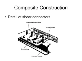
Steel Concrete Composite Beam Composite beams are normally hot rolled or fabricated steel sections that act compositely with the slab. The composite interaction is achieved by the attachment of shear connectors to the top flange of the beam. These connectors generally take the form of headed studs.
The composite action increases the load carrying capacity and stiffness of the beam by factors of up to 2 and 3.5 respectively. It is normally designed to be unproppedduring construction, and must be sized to support the self-weight of the slab, and other construction loads, in their non-composite state.
size of the steel section is governed by serviceability considerations because composite beams tend to be used for long span applications Check that beam deflections during construction will not lead to significant additional concrete loads (due to ponding) that have not been allowed for in the design The bending resistance of the section is normally evaluated using ‘plastic’ principles
The plastic moment resistance is calculated using idealized rectangular stress Blocks. It is assumed that stresses of fyd and 0.85 fcd can be achieved in the steel and concrete respectively
Composite beams are generally shallower (for any given span and loading) than non-composite beams, and they are used commonly in long span applications. Consequently, deflections are often critical.
Shear Connectors These connectors are designed to Transmit longitudinal shear along the interface prevent separation of steel beam and concrete slab at the interface
most common type of shear connector used in composite beams for buildings is a 19 mm diameter by either 100 mm or 125 mm long welded stud.
The property of shear connector most relevant to design is the relation-ship between the shear force transmitted, P, and the slip at the interface, s This load-slip curve should ideally be found from tests on composite beams.
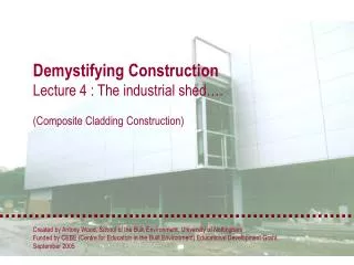
Composite slabs • consist of profiled steel decking with an in-situ reinforced concrete topping. • The decking(profiled steel sheeting) not only acts as permanent formwork to the concrete, but also provides sufficient shear bond with the concrete so that, when the concrete has gained strength, the two materials act together compositely • span between 3 m and 4.5 m onto supporting beams or walls
If the slab is unproppedduring construction, the decking alone resists the selfweight of the wet concrete and construction loads. Subsequent loads are applied to the composite section. If the slab is propped, all of the loads have to be resisted by the composite section. are usually designed as simply supported members in the normal condition
Profiled steel sheeting • depths ranging from 45 mm to over 200 mm • yield strengths ranging from 235 N/mm2 to at least 460 N/mm2 • .8 mm and 1.5 mm thick The various shapes provide Interlock between steel and concrete frictional mechanical
decking may also be used to stabilise the beams against lateral torsional buckling during construction. • stabilise the building as a whole by acting as a diaphragm to transfer wind loads to the walls and columns • temporary construction load usually governs the choice of decking profile
COMPOSITE COLUMNS A steel-concrete composite column is a compression member, comprising either a concrete encased hot-rolled steel section or a concrete filled tubular section of hot-rolled steel.
The presence of the concrete is allowed for in two ways. • protection from fire • It is assumed to Resist a small axial load • to reduce the effective slenderness of the steel member, which increases its resistance to axial load. The bending stiffness of steel columns of H-or I-section is much greater in the plane of the web (‘major-axis bending’) than in a plane parallel to the flanges (‘minor-axis bending’).
The ductility performance of circular type of columns is significantly better than rectangular types. There is no requirement to provide additional reinforcing steel for composite concrete filled tubular sections. corrosion protection is provided by concrete to steel sections in encased columns
While local buckling of the steel sections may be eliminated, the reduction in the compression resistance of the composite column due to overall buckling should definitely be allowed for. The plastic compression resistance of a composite cross-section represents the maximum load that can be applied to a short composite column.
Joints • Example of vertical shear transfer between beam and column
Aspects for using composite structures: • Architectural • Economical • Functionality • Service and Flexibility • Assembly
Aspects for using composite structures Architectural: • Longer spans • Thinner slabs • More slender column • More generous opportunities for design
Aspects for using composite structures Economical: • Reduction of height reduces the total of the building --> saving area of cladding • Longer spans with the same height --> column free rooms • Additional storeys with the same total height of building • Quicker time of erection: • Saving costs, earlier completion of the building • Lower financing costs • Ready for use earlier thus increasing rental income
Aspects for using composite structures Functionality: • Fire protection by using principles of reinforced concrete in which the concrete protects the steel
Aspects for using composite structures Service and building flexibility: • Adaptable structures • Modification during the life of the building • Modify services without violating the privacy of other occupants • Accommodation of service facilities in the ceiling within a false floor in a coffer box running along the walls
Aspects for using composite structures Assembly: • Working platforms of steel decking • Permanent shuttering • Reinforcement of profiled steel sheetings • Speed and simplicity of construction • Quality controlled products ensure greater accuracy
Construction methods Traditionally two counteracting methods of construction could be observed both connected with special advantages but also disadvantages worth mentioning. • Conventional concrete construction method • Construction in steel + high ratio between bearing capacity and weight + freedom of form and shapes + prefabrication + easy to handle + high accuracy + thermal resistance - low fire resistance - time-consuming shuttering - need of higher educated personal - sensitive on tensile forces
Construction methods • Composite Construction comparing these two methods a combination of both presents the most economic way + higher bearing capacity + higher stiffness + plastic redistribution
Examples Millennium Tower (Vienna - Austria) • 55 storeys • Total height 202 m • Total ground floor 38000 m2 • Capital expenditure about 145 million Euro • Time of erection: 8 months
42,3 m 33,05 m Concrete slab Concrete core Composite Slim floor beams Composite frame Composite columns 42,3 m Examples Millennium Tower (Vienna - Austria)
Examples Millennium Tower (Vienna - Austria) Total time of erection: 8 monthmax. speed 2 to 2.5 storeys per week!
Examples Parking deck “DEZ” (Innsbruck - Austria) Erection of composite columns over 2 storeys Assembly of prefabricated concrete slabs
Examples Parking deck “DEZ” (Innsbruck - Austria) • 4 storeys • Ground dimensions 60 x 30 m • Max. span length 10.58 m with 26 cm slim floor slab (= l/40)