Download
1 / 18
180 likes | 296 Views
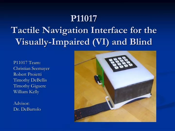
P11017 Tactile Navigation Interface for the Visually-Impaired (VI) and Blind. P11017 Team: Christian Seemayer Robert Proietti Timothy DeBellis Timothy Giguere William Kelly Advisor: Dr. DeBartolo. Today’s Agenda. Project Problem Statement Project Development from Customer Needs

E N D
P11017Tactile Navigation Interface for the Visually-Impaired (VI) and Blind P11017 Team: Christian Seemayer Robert Proietti Timothy DeBellis Timothy Giguere William Kelly Advisor: Dr. DeBartolo
Today’s Agenda • Project Problem Statement • Project Development from Customer Needs • Built System Design • Mechanical • Electrical • Software • Testing Summary • Future Project Developments
Problem Statement • Objective: Develop a device to aid the VI and blind in navigation throughout a building using a tactile interface. • Issues Faced: • Campus and Classroom navigation • Predominant use of memory for navigation • Current market technology unreliable and expensive • This is a combination of three Senior Design Projects: • Intra-Building Navigation • Tactile Navigation Interface • Mobile Landmark Identification
Mechanical System Design • Housing Structure • Top and Side walls constructed from HDPE and Garolite plastic. • Bottom is rapid-prototyped at RIT Brinkman Lab. • Directionality • Servo-driven tactile pegs • Tactile pegs made of HDPE • Proximity • Vibration Motor • Controlled by MCU to output 1 second vibrations
Mechanical System Design • Keypad • Clear bump on “5” button to understand # keys locations. • Orange bumps on side buttons as action keys. • Red rubber bump in bottom right acts as enter key.
Mechanical System Design • Attachment Method • Two elastic band straps. • Velcro attached to both at various locations. • Device attaches to user forearm toward elbow.
Electrical System Design Strategy Individually test components for functionality Prototype system using PIC development kit Create ‘front end’ user inputs Move design to PCB Verify power levels
Electrical System Design Built around an 8-bit PIC C-based microcontroller. Motors controlled by PIC and driven by BJT network. Keypad continuously polled in software, user entry stored in variable length string String will eventually compare to internal map to provide directional info 6V rechargeable NiMH battery Male/Female barrel connectors
Electrical System Design • PCB Design • 2 Layer Design • Created and manufactured using Express PCB • RIT CEMA soldered surface mount components
Software • Embedded C software written on to PIC18F8722 microcontroller • Prototyping used PIC DevKit • Functions • Continuously polls keypad to detect user input • Stores user input in string of variable length • Compares input to table of predefined commands • If match occurs, predefined action executed • Current Predefined Actions • Cardinal directions from Servos • Proximity with vibration motor
Future Project Developments Structural Ideas • Switch from Garolite to HDPE for housing wall material. • Addition of metallic threaded inserts • Prevents stripping the plastic threads • Correction of battery gap structural flaw. Software Ideas • Addition of Button Lock and Sleep Mode • Addition of Cancel Button • Change internal clock to reduce time between inputs • Add indicator for acceptable inputs
Future Project Developments Possible Design Improvements • Research of tubular solenoids instead of servos. • Customized battery and vibration motor to reduce size. • Expanding drawings tolerances to avoid extra machining. • Switch method for creating bottom housing. • Adjustable curvature to provide better fit for user.
Future Project Developments Optimization Ideas • Tactile Peg Locations • Locate optimal locations for pegs to reduce spacing • Creation of two part device • Part on hand and remainder in user pocket. • Reduces size on user forearm, therefore reducing attention drawn to user. • Reduction in device weight. • Wirelessly connected devices • Wi-fi or Bluetooth • Reduces device wiring • Integration with P11016 Intra-Building Navigation Team project.
Sponsors: National Science Foundation Acknowledgments: • Dr. Elizabeth Debartolo – Faculty Guide ME Department • Franklin LeGree • Dr. DorinPatru – EE Professor • Association of the Blind and Visually Impaired • P11016 Navigation Map Team • Dr. Marca Lam-Anderson – ME Professor • Mr. John Bonzo • Dr. Roy Melton – CE Professor • Mr. Jeff Lonneville – CEMA Lab Technician