Download
1 / 30
300 likes | 303 Views
MARS 2. Mechanical Design Review. Drive axes Orientation, location, & travel range of axes Typical axis drive configuration Axis loads, drives, encoders, & bearings. Optical mounts Manual adjustments Beam splitter Collimator Lenslet/camera Knife edge CCAS mounting

E N D
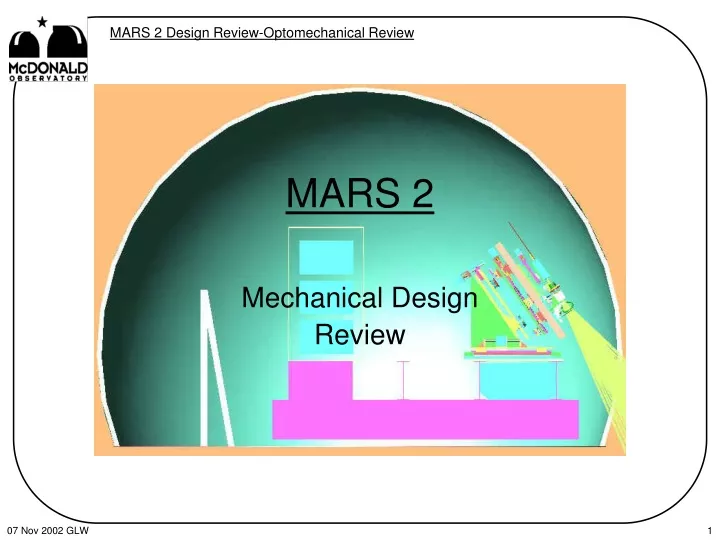
MARS 2 Mechanical Design Review
Drive axes Orientation, location, & travel range of axes Typical axis drive configuration Axis loads, drives, encoders, & bearings Optical mounts Manual adjustments Beam splitter Collimator Lenslet/camera Knife edge CCAS mounting Current design status Topics
MARS 2 Remote AxesTop to bottom • Wavescope camera • SenSys camera focus • Focus (Z) • X • Yaw (rotation about an axis parallel to Y) • Pitch (rotation about an axis parallel to X) • Y’ (combined with Focus to get Y)
MARS 2 Axes from Model Camera Focus Yaw Pitch Y’ SenSys X
Common Axis DriveComponents • For all BUT the SenSys axis • Stepper motor • Ball screw with preloaded drive nut • Limit and home switches • Encoder (absolute, rotary) • Fail-safe brake (not on camera axis) • SenSys camera axis • TS Products motor with internal encoder
Axis Drive Resolution • Stepper motor • 200 full steps per revolution • 10 msteps per full step • 2,000 msteps per revolution • Lead Screw • 2-mm per revolution lead screw • With mstepping results in 1 mm per mstep resolution • will need ~1/2 mm per mstep for yaw and pitch resolution • Absolute encoder • Parallel interface • Minimum encoder resolution of 2,000 counts per revolution will count each mstep
Axis Drive Loads • Worst case is “uphill” motion • Loads consist of: • Inertia load • Gravity component along axis • Friction • Encoder • Bearings • Drive screw • Others
Linear Axis Mounting • THK preloaded rails & bearings • Multiple rails with one block per rail • Slides mounted perpendicular to travel on one side will prevent binding due to misalignment & thermally induced dimensional changes • similar to bearing arrangement on the tracker carriage
dF & dL Stage Lead screw Yaw/Pitch Axis Mounting • Yaw axis • THK radial cross roller bearing for the pivot • THK curved bearing rail for additional support • similar to rho bearing on the carriage • Pitch axis will use flex pivots for the pivot • Yaw and Pitch axes will use flex pivots and small slides to accommodate dF (±2°) & dL (~0.3 mm) at the drive nut
Optical Mounts • Manual adjustments made with opposed adjusting screws where possible • Locks stage in position, does not rely on springs to hold stage against adjustment screw • Combination of flex pivots, pins, adjusting and clamping screws for yaw/pitch adjustments • X-Y-Z and X-Z cross roller stages for translation
Manual AdjustmentsPart 1 • Lenslet • x, y, yaw, pitch: aligns lenslet to optical axis • Lenslet/camera stage • focus: positions lenslet/camera wrt collimator • Collimator • x, y, yaw, pitch: aligns collimator to optical axis • focus: positions collimator wrt beam splitter cube • Beam splitter cube • x, y, focus, yaw, pitch: aligns cube to laser beam
Manual AdjustmentsPart 2 • Reference mirror • x, y, yaw, pitch: aligns mirror to optical axis • focus: positions mirror wrt HET focus • SenSys camera • x, y: positions camera wrt optical axis • Light source • x, y, focus: positions fiber wrt pin hole • Knife edge • focus: positions knife edge wrt beam splitter cube
Collimator Lenslet Reference Mirror Beam splitter Cube Knife Edge Isometric View of MARS2
Mounting in CCAS Tower • Remove everything down to 12-inch I-beams • Install stiffeners to forward cross beams • Install a layer of dampening material (plywood) • Install base plate • Incorporates gross translation & tip/tilt adjustments • Install base wedge with y’-axis • Install pitch, yaw, & x-axis assembly • Install assembled optical bench with focus axis • Install electronics rack
CCAS Components Electronics rack Base plate Dampening material 12-inch I-beam members Frame stiffener
Current Design Status • Most purchased components are identified • Final layout work & mounting details need to be completed • Drive configuration needs to be finalized • Laser for component alignment needs to be added • Drawing generation is the next big task
Unknowns • Tolerance analysis • Metal finishing-is it needed?
Top View of MARS2 SenSys Camera Light Source Knife Edge Lenslet Camera Pellicle Collimator Reference Mirror Beam splitter Cube
Camera Focus Y Yaw X Pitch SenSys Y’ Relative Axis LocationsSide View
SF = ma Fdrive-Ffr-W*cos(a) = m*a and with m = W/gc Fdrive-Ffr-W*cos(a) = W*a/gc Fdrive = Ffr + W*[cos(a) + a/gc] + Fdrive a Ffr W cos(a) W rearranging Axis Drive Loadsin pictures and equations Note that: • a = 35° >> cos(35°) = 0.82 • gc = 386.4 in/sec2 >> for small a’s, cos(a) dominates • used a = 10 in/sec2 in calculations • Not all axes have a W cos(a) component
Motor produces torque Drive nut converts torque to force Force * Lead Torque = 2 * p * e Torque to Load Drive coupling Ball screw with xx lead (pitch) e = efficiency of ball screw, ~ 0.85-0.90
Axis Drive Specifics • IMS stepper motor • two sizes to cover six axes • dual shaft • Schneeberger ball screw • 12-mm diameter for all but camera axis • 3,400 N (770 lbf) static load s. f. min = 4.2 • 2,500 N (565 lbf) dynamic load (L10) s. f. min= 3.1 • preloaded drive nut • special order for length and end configuration • Absolute rotary encoder • parallel output • multi turn (25 turns needed) • 4,096 steps per revolution • 2 encoder steps/1 mm • 1 encoder step /0.5 mm • Electroid fail-safe brake • engages with power off