Download
1 / 31
320 likes | 416 Views
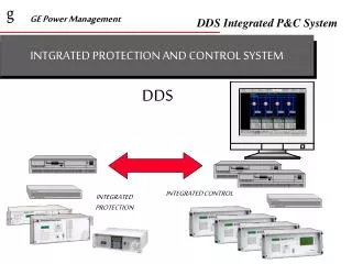
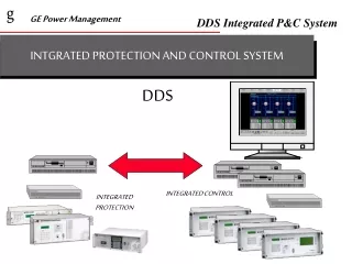
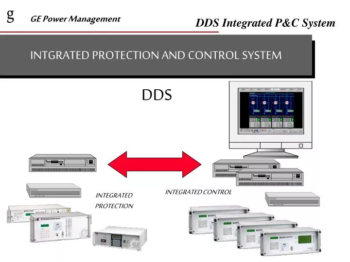
INTGRATED PROTECTION AND CONTROL SYSTEM. DDS. INTEGRATED CONTROL. INTEGRATED PROTECTION. APPLICATION FIELDS. SUB-TRANSMISSION SUBSTATIONS DOUBLE/SINGLE BUSBAR LAYOUTS, BREAKER AND A HALF ETC. DISTRIBUTION SUBSTATIONS SINGLE AND DOUBLE BUSBAR LAYOUTS TRANSMISSION SUBSTATIONS

E N D
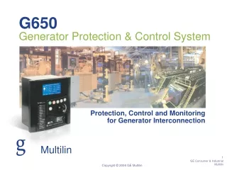
INTGRATED PROTECTION AND CONTROL SYSTEM DDS INTEGRATED CONTROL INTEGRATED PROTECTION
APPLICATION FIELDS • SUB-TRANSMISSION SUBSTATIONS • DOUBLE/SINGLE BUSBAR LAYOUTS, BREAKER AND A HALF ETC. • DISTRIBUTION SUBSTATIONS • SINGLE AND DOUBLE BUSBAR LAYOUTS • TRANSMISSION SUBSTATIONS • NO KV LIMITATION
Traditional SCADA RTU Power Supply Neutral Current Transducer Remote Terminal Unit Voltage Transducer Modem Phase Current Transducer kW/kVAR Transducer Radio Power Factor Transducer Other Transducers CT´s Outputs Inputs CT´s Host Alarms and Trips Protection Relay
GE PM SOLUTION CT´s VT´s Analog Inputs Digital Inputs Comm. Port Digital Outputs DMS INTEGRATED MODULE
DMS Units Hardware Module Commun. CPU Control CPU CONTROL SUB-MODULE • Power Supply Module • (possible redundancy) • Magnetic Module: 8 CT/VT • Digital Inputs: 21 • Digital Outputs: 12 • Digital I/O: 7 inputs • 8 outputs • Analog inputs module, 4 inputs • CPU: 16 bit MP based • Communications CPU: 16 bit MP based, RS-232, RS-485, Fiber Optics communications available. • Front bus + MMI module • (+ Graphic LCD + 6 control keys)
DMS UNITS CONTROL FUNCTIONS • SWITCHGEAR CONTROL • Up to 7 switchgear (or dynamic elements) control and real time monitoring. • MIMIC DISPLAY • Allows real time monitoring (1 or 2 contacts selectable) and local operation of switchgear.
DMS UNITS CONTROL FUNCTIONS • METERING • Default metering for every unit: Ia, Ib, Ic, In, I2, Vab, Vbc, Vca, Vbus, P, Q, f, Cos phi.
DMS UNITS CONTROL FUNCTIONS • ALARMS PANEL • 96 Configurable alarms (32 protection, 48 control, 16 comm.) • Alarm format: Date, time, Description text. • Alarm status(active/non active, acknowledged/not acknowledged) • Alarm acknowledgement through graphical display (local HMI)
DMS UNITS CONTROL FUNCTIONS • OPERATIONS & BAY INTERLOCKINGS • Up to 16 operations: 2 fixed (block / unblock control) 14 programmable operations • Configurable parameters for each operation. • Operation description (text) • Operation conditions (4 per operation) • Failure conditions (3 per operation) • Success conditions (1 per operation) • Timers Operation • Output 1 per operation • Success • Operation confirm • Up to 4 programmable “static” interlockings.
DMS UNITS CONTROL FUNCTIONS • Analog inputs: • Up to 4 chanels • Selectable (each one independently) as: 0-1 mA, 0-5 mA, 4-20 mA, -2.5/+2.5 mA, -10/10 V. • Pulse Inputs: (Any digital input can be a pulse counting input) • 9 digit counter (up to 999999999 Kwh or Mwh) • 1-65000 Kwh per pulse • 4 choices KWh, KVArh, MWh, MVArh • Inputs for tap load changer position monitoring: • Up to 8 digital inputs in Gray/BCD/Binary code or through analog input.
TRANSMISSION SUBSTATIONS CONTROL PROTECTION CAPTURE CAPTURE SUBSTATION ARCHITECTURE GENERAL APPLICATION REMOTE CONTROL LEVEL 3 IEC 870-5 • SCHEMES: • Breaker and a half • Double busbar • Single busbar LEVEL 2 LEVEL 1 • Protection and Control for: • Line • Transformer • Busbars LEVEL 0
Protection System Integration Architecture Phone Access CONTROL OTHER IED´S IEC870-5-101 LEVEL 2 GPS Sync. FAC Transmission Lines HV Bays LEVEL 1 PC laptop for local access ALPS RELAY MV Bays Transformer Bays
Control System Architecture (LEVEL 3) GENESIS SOFTWARE SCADA Printer PROTECTIONS Modem LEVEL 2 PC Dual Available LEVEL 1 units: DMS, DTP, DFF, DBF, DRS, MOV, DTR, SMOR, ALPS GPS Sync. IEC870-101 FAC HV Bays PC laptop for local access MLINK 115 kbps LEVEL 1 Communication channel MV Bays Transformer Bays
SUBSTATION BAYS • SUB-TRANSMISSION OR DISTRIBUTION HV LINE • HV BUS COUPLER & METERING • POWER TRANSFORMER • MV FEEDER • CAPACITOR BANK • MV BUS COUPLER & METERING • AUXILIARY/GENERAL SERVICES
g Detail of Level 2 with Redundancy Serv-Switch IEC 870/5- 101 SCREEN Modem RAID 2 Power Supplies RS-232 Switch SCSI Bus SCSI Bus KEYBOARD MOUSE CPU - 1 CPU - 2 TCP/IP RS232 Modem RS-232 Switch IEC 870/5- 101 FAC2000 PROTECTIONS DMS (x number of units) Available LEVEL 1 units : DMS, DTP, DFF, DBF, DRS, DTR, MOV, SMOR, ALPS DTP (x number of units)
LEVEL 2 CONTROL FUNCTIONS • CONTROL FUNCTIONS • Programmable configuration of the substation • Control of the HV equipment • Switchgear status indication • Instantaneous metering of the substation • Programmable Interlockings between bays • Automatic Functions - Load shedding for under voltage/frequency - Sequential Operations between bays - Reactive power control combined with transformer tap changer
LEVEL 2 CONTROL FUNCTIONS • CONTROL FUNCTIONS (Cont.) • Metering Tariffication • Alarm Treatment • Maintenance Engineering - Breaker monitoring (I2 t) • Substation event register • RTU for connection to remote central dispatching centers
GE-NESIS WINDOWS BASED SOFTWARE WITH APPLICATIONS GE_LOCAL GE_INTRO GE_OSC GE_POWER GE_CONF GE_FILE
APPLICATIONS DESCRIPTION GE-LOCAL: LOCAL COMMUNICATION FOR SETTINGS, INFORMATION REQUEST AND ON-LINE VIEW OF PARAMETERS • Single line diagram position view, including status and metering values. • Access to information: Status, Metering, Events, Oscillography and Alarms for every position. • Viewing and change of settings. • Access to Bay operations
APPLICATIONS DESCRIPTION GE_LOCAL
APPLICATIONS DESCRIPTION GE-INTRO: CONFIGURATION AND ASSIGNMENT OF THE DDS INPUTS/OUTPUTS, ALARMS AND CONTROL LOGIC Function: • Protection inputs, outputs & events configuration. • Control inputs, outputs & events configuration. • Control programming. • Alarm configuration • Graphical display configuration
APPLICATIONS DESCRIPTION GE_INTRO
APPLICATIONS DESCRIPTION GE-POWER: LEVEL 2 PROGRAM THAT ALLOWS REAL-TIME CONNECTION TO LEVEL 1 DEVICES • Single line Substation diagram including metering values and status. • Zoomed single line diagrams per position. • Access to information: Status, Metering, Events, Oscillography and Alarms for every position. • Remote viewing and change of settings. • Access to switchgear operation.
APPLICATIONS DESCRIPTION GE-CONF: SUBSTATION CONFIGURATION Functions: • User configuration, privileges and passwords. • Position configuration. • Per position: Status, metering and values configuration for transfer to level 2. • Per substation Data base generation.
APPLICATIONS DESCRIPTION GE_POWER GE_CONF
APPLICATIONS DESCRIPTION GE_POWER GE_CONF
APPLICATIONS DESCRIPTION GE_POWER GE_CONF
APPLICATIONS DESCRIPTION GE-FILE: REPORTS AND DEMAND PROFILE GENERATION Functions: • Events, logs, alarms, etc. report generator • Operation reports and Demand Profile generation per bay.
APPLICATIONS DESCRIPTION GE_FILE
APPLICATIONS DESCRIPTION GE-OSC: OSCILLOGRAPHY RECORDS DISPLAY AND ANALYSIS Functions: • Displays COMTRADE files (ASCII or binary), including: • Waveform • Fasors • Fault reports • Digital signals operations • R-X Diagram module for distance relays analysis.
APPLICATIONS DESCRIPTION GE_OSC