Download
1 / 19
190 likes | 293 Views
MICROPROCESSOR BASED SYSTEM DESIGN. Lecture # 09 - 10. BY PROF. DR. B. S. CHOWDHRY PROF. DR. WAJIHA SHAH. Memory Address Space & Data Organization. How information such as numbers, characters & instruction: are stored in Memory? 8088 microcomputer supports 1M memory.

E N D
MICROPROCESSOR BASED SYSTEM DESIGN Lecture # 09 - 10 BY PROF. DR. B. S. CHOWDHRY PROF. DR. WAJIHA SHAH
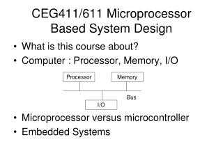
Memory Address Space & Data Organization • How information such as numbers, characters & instruction: are stored in Memory? • 8088 microcomputer supports 1M memory. • Memory space organized as bytes of data stored at consecutive address over address range 0000016 to FFFFF16. • Memory in 8088-based microcomputer is actually organized as 8-bit bytes, not a 16-bit words.
Memory Address Space & Data Organization (Cont..) • However, 8088 can access any two consecutive bytes of as a word of data. • The lower-address byte is the Least Significant byte of the word and the higher addressed byte is Most Significant byte of the word.
Memory Address Space & Data Organization (Cont..) Fig. Storing a word of data in memory • These two bytes represent the word 0101 0101 000000102 = 550216
Data formats of 8088 are: - bytes (8-bit) - word (16-bit) - double word (32-bit). • The 8088 MP can directly process data expressed in number of different types: • Unsigned integer number • Signed integer number. Each integer can be either byte wide or word wide: • Unsigned byte integer number (0 to 255) • Signed bytes integer number (-128 to +127) • Unsigned word integer number (0 to 65435) • Signed word integer number (-32768 to +32767) • ASCII numbers are stored one number byte.
Generation a Memory Address • A logical address in the 8088 system is described by a SEGMENT & OFFSET. • Both the segment & offset are 16-bit size. • This is because all registers and memory locations are 16-bits long. • However, the PHYSICAL ADDRESSES that are used to access memory are 20-bits in length. • Addresses are expressed in one of two hexadecimal formats: - A 32-bit Segment-offset address, which combines a base location (Segment) with an Offset to represent an actual location. e.g. 08F1: 0100.
Generation a Memory Address (Cont..) • A 20-bit Absolute address, which refers to an exact memory location. e.g. 0901016 • To illustrate, let us start with a hypothetical segment-offset address of 08F1: 0100. • The CPU automatically converts this to a 20-bit absolute address by adding the segment and offset together. • The segment value is always understood to have 4 implied zero bits to the right. • Therefore, a segment address of 08F1 h really represents an absolute location of: 08F10 h: 0 8 F 1 (0) 4 implied bits 0000 1000 1111 0001 0000
The MPU then adds the offset to the segment, yielding the absolute address: Segment value 0 8 F 1 (0) Add the offset 0 1 0 0 ____________ 0 9 0 1 0 • Advantage: Program can access large memory by setting the current segment address to a new block of memory. • The generation of physical address involves combining a 16-bit offset value that is located in a Base Pointer (BP), Index Registers, (SI or DI) or a Instruction Pointer Register (IP), and a 16-bit base value that is located in one of the Segment Registers (CS, SS, DS, ES).
For example, when an instruction acquisition takes place, the source of the base address is always CS register & the source of the offset is always the IP. The physical address can be denoted as CS: IP. • On the other hand, if the value of a variable is being written to memory during execution of an instruction, typically, the base address will be in DS register, and the offset will be in DS register. The physical address can be denoted as DS: DI. Another example is the stack address that is needed when pushing parameters onto the stack. This address is formed from the contents of the (SS & SP).
Problems: What would be the offset requires to map to physical location 002C316 it the segment base address is 002A16? • Solutions: The offset value can be obtained by shifting the segment base address left 4-bit and than subtracting it from physical address. Shifting left 4-bit gives: 002A016 Now, subtracting, we get the value of the offset. 0 0 2 C 3 - 0 0 2 A 0 0 0 2 316 Note: (1) This address calculation is automatically done within 8088 each time a memory access in initiated. (2) Segment register are user accessible. This means that the programmer can change the value they hold through software.
The programming model of the 8086 through the Pentium Pro Processor is considered PROGRAM VISIBLE because its registers are used during programming and are specified by the instructions. • The 8086, 8088, and 80286 microprocessors contain 16-bit internal architectures. • The 80386, 80486, Pentium and Pentium Pro microprocessors contain full 32-bit internal architectures. • The PIII, PIV has got 64/128 bit internal architectures (Data bus 64-bit only).
The architectures of the earlier 8086 through the 8086 are full upward compatible to the 80386 through Pentium Processors. • The extended 32-bit registers are lebled EAX, 1 BX, ECX, EDX, ESP, EBP, EDI, ESI, EIP, and EFLAGS. • FS, GS are also available on 80386 and above. The FS and GS are supplemental segment registersto allow two additional memory segment for access by programs.
Example: Design an interface for heating control system of TPS based 8-bit microprocessor. Choose a suitable memory allocation to minimize the input and output address decoding for an application requiring a program of 4kpytes plus 2 input and output ports. Solution: • Program memory = 4k • Can be stored in the bottom 32k A15 = 0 RAM is selected = 1 I/O is selected.
Address Decoder: Minimal Address Decoding • Address decoder is needed for both the input and output interface, to ensure that the interface appears on the data bus only for one specific memory location otherwise memory contention could occur between data and program memory & input and output ports. • Logic circuitry is needed to select one unique memory location from a 64k bytes address space. • In a memory mapped input computer, this circuitry can be reduced by minimal address decoding that means in a typical dedicated microprocessor application only a small part of the complete address space is used.
A0-A1 are decoded to select one of 4 interfaces. • A2 to A14 are not connected to I/O Interfaces. • The I/O interface thus appears at the addresses: • $8000 $8001, $8002, $8003 • and replicated at, • $8004, $8005 $8006, $8007 ……… • $FFFC, $FFFD, $FFFE, $FFFF
Comment: The solution is not unique • I/O port addresses could equally be reversed. • Three address lines need to be decoded rather than all 16. • This is called minimal address decoding.