Download
1 / 29
490 likes | 846 Views
“Challenge the Dominant Paradigm”. Mission Engineering TM - a transformational business analysis and system engineering approach. Mission Engineering (ME) Defined. ME is an advanced requirements gathering and analysis method

E N D
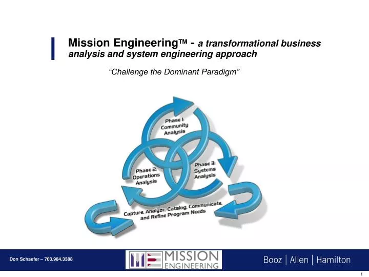
“Challenge the Dominant Paradigm” Mission EngineeringTM - a transformational business analysis and system engineering approach
Mission Engineering (ME) Defined • ME is an advanced requirements gathering and analysis method • ME is focused on capturing & translating the ‘intent’ of the customer’s mission needs into implementable system/software/data requirements • ME reduces interpretation of textual requirements by using visually robust products as the central communication device • ME provides notational linkage of the implementable requirements to the originating customer mission needs • ME is an engineering method that can be used with any system or software engineering processME is a repeatable method where all of the processes and artifacts can be used, or it can be tailored with only a subset of the overall method • ME analysis and artifacts support acquisition analysis, BOE costing and portfolio management. ANALYSIS, COMMUNICATION & UNDERSTANDING
Why Was Mission Engineering Developed? • Deliver systems with greater user satisfaction • Speed up design and development time • Provide analytical defendabletraceability from customer need to architecture design • Provide a better way to derive/illustrate COTS/GOTS/Technology integration requirements • Identify the risk…technical, operational and programmatic • Provide a more integrated and holistic view of the enterprise Customers spend millions of dollars…purchase the best hardware, the best software, and the best engineers…and if the users don’t like or use the system…the system development was a failure
OperationalView Identifies What Needs to be Accomplished and Who Does It SystemsView Technical StandardsView Relates Systems and Characteristics to Operational Needs Prescribes Standards and Conventions Mission Engineering and the DODAF Pyramid • What Needs to Be Done • Who Does It • Information Exchanges Required to Get It Done • Operational Requirements and Capabilities • Systems that Support the Activities and Information Exchanges • Basic Technology Supportability • New Technical Capabilities • Specific System Capabilities Required to Satisfy Information exchange • Technical standards Criteria Governing Interoperable Implementation/Procurement of the Selected System Capabilities
Program Office Community Analysis Community Model Interface Transaction Inventory Visual Con Ops Advocacy Products - CV Business Rule Conflict Risk Areas & Opportunities Prioritization of EAR - Activities Community Community Mission Engineering Client Information Existing Ops Cons & Req Legacy systems Constraints Community Feedback Launch & Learn via Portal Operations Analysis Enterprise Activity Roadmap Concept Visualization Mission Process Mapping Technology Mapping INPUT To… Fault Isolation Problem Isolation Systems Analysis Multiple Dimensional Requirement's Reqt’s Mapping to Activities Derive Requirements Risk Analysis Requirement's Visualization Operational Scenarios CONCEPT OPERATIONS INPUT To… Field Documentation (Manuals) Training Material Development INPUT To… ICD Identification Actor/Organization Interfaces SPECIFICATION DEPLOYMENT INPUT To…Detail Design Actor Inventory Visualization & GUI design Use Case Description Activity / Sequence / etc…UML COTS/GOTS/Custom Code Integration Opportunities Used To… Validate design ARCHITECTURE VERIFICATION INPUT To… COTS/GOTS Integration DESIGN INTEGRATION INPUT To… Test Plan & Procedures DEVELOPMENT TEST ACQUISITION / CONSTRUCTION
Mission Engineering – What it will do, what it won’t do • Mission EngineeringWILL: • Provide your program with enough functional requirements and preliminary design content to get you to your programs Preliminary Design Review (PDR) gate • Provide your program with a ‘conceptual’ design of the system/application • Provide your program with high level business process flows that are linked to requirements • Provide data architects with a preliminary first draft data dictionary • Provide software architects with a complete workflow analysis, functional behaviors and interface points for COTS integration • Provide Business Process Analysts with lower level (level 5) process flows and business rules • Provide Test engineers with a first draft of the system test procedures • Provide Test engineers with multiple Mission and Capability functional threads • Provide Trainers with input to both standup and/or computer based training course material development • Provide system engineers and architects with preliminary interface definitions and architectural behaviors • Provide stakeholders (Customers) with an easily understood view of what will be developed and how it will be used • Provide your program high quality, rigorous, analytical business and engineering content…if you have the right team • Mission Engineeringwill NOT: • Provide your program with detailed design; e.g. logical model, physical model, UML • Provide you with ‘system’ level requirements; e.g. –ilities (maintainability, scaleability, etc), network protocals, etc • Provide you with hardware requirements • Provide you with network requirements, etc • Be useful to the program if you do not have the right team working on the analysis.
Phases of Mission Engineering Customer Need Engineering Reqt’s ANALYSIS, COMMUNICATION & UNDERSTANDING
Mission Engineering Phase I – Community Analysis Process • INPUTS • Goals • Processes • Products • Existing Documents • User Types • TEAM • Customer • Domain Analysts • Mission Eng Analyst • Desktop Multimedia Producer • Additional Products • Visual Operations & Requirements Spec • Concept Visualizations • Advocacy Material • Requirements • Standardized Architectural Views e.g. C4ISR • Value Engineering Core Products • Community Interface Model • Transaction Inventory • Actor Inventory • Background Information • Input To: • Arch Analysis • Program Marketing • Training • Reqt’s Analysis • ICD Development
Community Analysis – Advocacy & Understanding Develop understanding and advocacy for Customer's Goals and Transformation • Analyze and Define: • Mission Customers, Mission Partners • Mission Roles: Analyst, Consumer, Collection Manager • Information transactions • Information developed & delivered among roles • Value Chain & Capabilities ME Traceability Develop Information Transaction Inventory EAR Activity When transacted Network Domain EAR Service Area Transaction ID Info Type Develop Concept Visualization Info Received From Info Sent From Develop Community Model
Phase 1 Summary of content • At this point, we should have developed: • First draft of community model • Beginning of the actor list • Beginning of the tools (COTS/GOTS) list • Supplier list • Customer list • Partner list • Information Transaction table • TIME Elapsed: 1 to 3 weeks • Additionally, if the program desires, we should also begin the story board for the concept visualization work
Mission Engineering Phase II – Operations Analysis Process • TEAM • Customer • Domain Experts • Business Analysts • Mission Eng Analyst • Information Architect • System Arch • Additional Products • Business/Mission Process Analysis • Technology Evaluation Matrix • Mission Threads/Product Threads • Actor and Activity Matrix • Requirements Analysis • C4ISR Views • Output To: • Community Model Updates • ME Phase 3 • BPR activities • Program Marketing • Strategic Acquisition Core Products • Enterprise Activity Roadmap • Activity Goals & Descriptions • Capability Descriptions • Enterprise Activity Function Map • Mission Process Models
The Enterprise Activity Roadmap is developed in an Integrated Product Team environment • Work with stakeholders on the mission of the organization and the product & service value chain scenarios from a task flow perspective. • Identify high level “Mission or Operational” Service Areas • Identify “functional activities” involved within the system workflow…logical groupings • Create an inventory illustrating the actor functional activities required in the performance of their mission or in production of a product or service
Enterprise Activity Roadmap defined… Operational Services Functional Activities Increment 1 Increment 2 Increment 3 Commercial Tool A Commercial Tool B Legacy App 1 Activity Name: Activity Code: Actor Class; Actor: Pre-: Post-: COTS/GOTS: Arch service: Source: No Tool ID
Functional Breakdown of COTS/GOTS tools • There are two ways to map tools to the activity roadmap; complete tool or tool function. • For instance, in the illustration below, lets assume the yellow icon represents the Microsoft Office Tool. • As the MS Office tool, you can see exactly what activities have been identified that the MS Office tool will be used or integrated. • Or, if you break MS Office into its high level component functions, (e.g. E-Mail, Notes, Tasks, Contacts, Calendar), you would see which activities will use MS Office, but, you could also then see which component of MS office as well. • You would have: • OL-C – outlook-calendar • OL-E – outlook-e-mail • OL-N – outlook-notes Add COTS/GOTS component as an attribute to activity
Mission Process Map (MPM) Overview A Mission Process Map (MPM) shows the BPR results in the context of a Mission thread. The steps in the MPM are mapped directly to the Activities in the Roadmaps and Service Areas in the Community Model Activities mapped to the Roadmap Service Area Identifier
Phase 2 Summary of content • At this point, we should have: • First draft of every enterprise ‘segment’ activity roadmap • Full definition of each service area • Written all goals and descriptions for all activities • Begun to prioritize the activities per client needs, implementation schedule and funding • A number of Mission Process Maps completed, may include state changes • A candidate set of Capability Vignettes completed or identified • Full description of each actor role • Mapped actor roles to activities • Functional breakdown of tools • Mapped Tools/functions to activities • Listed ‘source’ for each activity, e.g. document, legacy, person • Final draft of the Community model with Service areas shown • TIME Elapsed: 2 to 6 weeks
Mission Engineering Phase III – Systems Analysis Process • TEAM • Domain Experts • Architects – SW, DB, SYS, SEC, Info • Mission Eng Analyst • Mission Eng Facilitator • Additional Outputs • System Requirements • Enterprise Requirements Documents • Business Process Analysis • Requirements Mapping • Requirements Traceability Matrix • Requirements Visualization • Information Architecture • Output To: • Tool Evaluation • Testing Procedures • Training • Architecture • Field Documentation • SW Detailed Design • DB Design • BPR Core Outputs • Functional Requirements • Data Elements and Attributes • Multidimensional Requirements View • Data Tables/Relationships • Business Rule to Function Mapping
System Requirements – Workflow, Interfaces, Behaviors Multi-Dimensional Requirements View (MRV) • Created in an IPT environment of stakeholder, developers and integrators • Captures the activity workflow of people and systems • Captures the behaviors between functions, applications and data • Derives new requirements from integrated architecture analysis • Provides framework to map existing legacy requirements Requirements Visualization EAR MRV Service Area Define operational functional steps – activity workflow Activity Map ops functions to system layer applications Web viewable; DOORS, RequistPRO Map data created & data read to functions Derive new requirements, map existing requirements Central Repository Derive and/or Map business rules to functions
MRV to RV development…”test drive the requirements prior to development”
MRVs explained & link to rest of program Business Segment User Role Business Segment Activity Business Segment Service Area Activity Functional Steps Architecture Segments – Application COTS/GOTS interface Data Store Name – Read / Write Activity Functional Requirements Activity Function Business Rules Maps Activity / Requirements to Capabilities on CDR Criteria for Tech Evaluation Input to Software Design Input to Test Procedures Input to Training Scenarios Input to User Experience Input to Information Architecture Input to TE Business Process Analysis DOORS Database
Phase 3 Summary of content • At this point, you should: • Begin development of the integrated Ops and Requirements Document • Completed a first draft of the prioritized MRVs • Defined performance goals for each MRV to the level required • Can begin development of the data dictionary from each MRV • Analyze the COTS/GOTS functional interfaces for integration • Updated the Community model • Updated the Activity Roadmaps • Updated the Business process flows • TIME Elapsed: 1 to 3 MRVs per day
The Linkage Multidimensional Requirements View (MRV) Community Model Requirements to Architecture View (RAV) Activity Perform Ballistic Missile Optimization ACT Code: OP-PBMOP Actor: PA, PL Arch CSCI: OPTIMZ COTS/GOTS: ILOG, IMEA, JMEM, MEM, MGPS CSCs Mission Ops Activity Roadmap Missile Defense Mission Thread MCP 0042 Deliver Basic Detailed Planning Optimization
NGA Community Model Activity Roadmaps Communications Users work with Geoscout to determine activity and service needs User Groups from NGA Mission Segments; GIO, Corp, Funct, ITM Business Processes from each Mission Segment 1 for 1 relationship of user activity to MRV Users drive Ops function needs in MRV-member of design team Users support Business Process Analysis & Mission Process Mapping Stakeholder Insight Users validate Information Architecture Users evaluate prototypes and tools Multidimensional Requirements View (MRV) Requirements Viz & Tech Demos NSGI Site Map Activity Mapping to Mission Threads & Business Processes
Now Now Next Next After Next After Next BLOCKS BLOCKS Capabilities Capabilities Capability Delivery Roadmap Capability Delivery Roadmap Mission Engineering Summary User & Stakeholder Input Business Cases Developer Input & Ideas Legacy System Requirements Capability Value Chains Strategic Analysis INPUT PRESENTATION & ANALYSIS User Validated Operational Concept Training Input Requirement’s Validation: Mapping Requirements to Functionality Information Architecture Business Objects Use Case Input Interface Design Activity Diagrams Sequence Diagrams Technology Evaluations Risk Identification Etc… Deferred / Derived Requirements Test Plan & Procedures BPR Tasks OUTPUT Converting Needs into Requirements , Communicating Results
Client Project Name Client Project Name NGA Integrated Exploitation Capability (IEC) NRO XOComm Air Force Space Based Blue Force Tracking NGA Big Idea DISA Traces2 NSA Stone Mason Joint Staff Airborne ISR Requirements Based Allocation DIA HUMINT/CI Comms Architecture Eval DIA JIVA DISA Meteorological Info System Terminal (MIST) SPAWAR Strike Fighter Training System (SFTS) NGA GeoScout Booz Allen Has Successfully Applied Mission Engineering to a Wide Range of Clients and Products
Value and benefits of using Mission Engineering • Fosters Communication and Understanding • Translates mission needs into engineering requirements • Reduces interpretation of textual requirement • Illustrates user functions within work flow • Illustrates COTS/GOTS/Custom code integration/interfaces • Supports the early identification of risk; technical, business and program • Supports product/artifact reuse across the system/software engineering lifecycle • Support the development of test and training material • Supports development of DODAF views


![CloudSat System Engineering Report [ Mission Performance]](https://cdn2.slideserve.com/5199370/slide1-dt.jpg)