Download
1 / 40
400 likes | 512 Views
Thermal Shock Measurements for Solid High-Power Targets at High Temperatures. J. R. J. Bennett 1 , G. Skoro 2 , J. Back 3 , S. Brooks 1 , R. Brownsword 1 , C. J. Densham 1 , R. Edgecock 1 , S. Gray 1 and A. J. McFarland 1 1 Rutherford Appleton Laboratory, Chilton, Didcot, Oxon. OX11 0QX, UK

E N D
Thermal Shock Measurements for Solid High-Power Targets at High Temperatures J. R. J. Bennett1, G. Skoro2,J. Back3,S. Brooks1, R. Brownsword1, C. J. Densham1, R. Edgecock1, S. Gray1 and A. J. McFarland1 1 Rutherford Appleton Laboratory, Chilton, Didcot, Oxon. OX11 0QX, UK 2 Department of Physics and Astronomy, University of Sheffield, Sheffield. S3 7RH, UK 3 Department of Physics, University of Warwick, Coventry. CV4 7AL, UK roger.bennett@rl.ac.uk Joint high power target meeting, EURISOL/BENE, CERN, 22 February 2007
OUTLINE • Introduction • Thermal Shock, Fatigue and Creep • Wire tests • Future work
The original RAL Target concept - (after Bruce King)
Schematic diagram of the radiation cooled rotating toroidal target rotating toroid toroid magnetically levitated and driven by linear motors solenoid magnet toroid at 2300 K radiates heat to water-cooled surroundings proton beam
The alternative concept – Individual Bar Targets
Target Parameters Proton Beam pulsed 50 Hz pulse length ~40 s energy ~10 GeV average power ~4 MW Target (not a stopping target) mean power dissipation 1 MW energy dissipated/pulse 20 kJ (50 Hz) energy density 300 J cm-3 (50 Hz) beam 2 cm 20 cm
solenoids Target Bars Proton beam The target bars are connected by links - like a bicycle chain. Schematic diagram of the target and collector solenoid arrangement
Thermal Shock The Perceived Primary Problem
The value of the peak stress is: With typical values for tungsten: E = 300 GPa α = 0.9x10⁻⁵ K-1 T = 100 K 0.2% Yield Strength = ~20 MPa at 2000 K UTS = ~100 MPa σmax = 270 MPa Stress exceeds UTS FAILURE EXPECTED!!
Real Life is not this simple. - The Pbar target at FNAL withstands 40,000 J cm-3! - The NF target has only 300 J cm-3
Individual pulses are not the problem. Failure found after Many Pulses – the problem is:- Fatigue & Creep
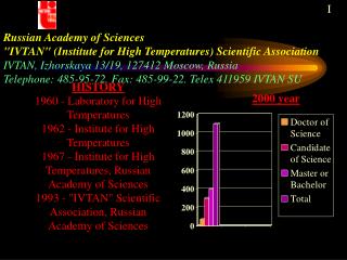
Fatigue and Creep Very difficult to predict the number of cycles to failure. S-N or Wöhler Plot – stress versus number of cycles to failure. The Fatigue Limit Stress can be expressed by: σ0 = 1.6 Hv ± 0.1Hv Hv - Vickers Hardness in kgf mm-2 For tungsten at ~1800 K Hv = 50 so the fatigue limit stress is σ0 = 80 MPa Stress, S σ0 N = ~106 Number of cycles, N (log scale)
The primary purpose of these tests is to address the problem of thermal shock at high temperatures. To find a refractory material that will withstand the thermal stresses/fatigue and have a long life of ~1-10 years. 1 year corresponds to 106 pulses on an individual target bar.
It is not possible to test the full size targets in a proton beam and do a life test. The solution • Produce shocks by passing high current pulses through thin wires.
Lorenz Force Thermal Force Lorenz + Thermal Force 100 ns pulse Typical radial stress in the wire from thermal and Lorentz forces Goran Skoro
Radial characteristic time 3 micro-pulses in 2 cm diameter target micro-pulse macro-pulse 3 micro-pulses in 3 cm diameter target 5 micro-pulses in 3 cm diameter target Macro-pulse length, ms Goran Skoro
Wire: 0.5 mm diameter, 3 cm long; 800 ns long pulse, exponential rise, 100 ns rise time 3 cm diameter target 2 cm diameter target Peak current [kA] Isostress* lines for tungsten target and wire (operating at 2000 K) Results * - Von Mises stress Beam power [MW] Target: repetition rate = 50 Hz; beam energy = 6 GeV; beam radius = target radius 3 x 2 ns long micro-pulses; macro-pulse length = 20 s (2cm x 17cm), 25 s (3cm x 20cm); Energy deposition = MARS Goran Skoro LS-DYNA
Test wire, 0.5 mm Φ Pulsed Power Supply. 0-60 kV; 0-10000 A 100 ns rise and fall time 800 ns flat top Repetition rate 50 Hz or sub-multiples of 2 Coaxial wires Vacuum chamber, 2x10⁻⁷ -1x10⁻⁶ mbar Schematic circuit diagram of the wire test equipment
test wire ISO 63 cross ct Penning gauge 8 Co-axial cables window 4 support rods Top plate window ISO 63 tee Electrical return copper strip bulkhead high voltage feed-throughs turbopump Schematic section of the wire test assembly
Vertical Section through the Wire Test Apparatus Spring clips Sliding connection Two graphite (copper) wedges Current Tungsten wire Stainless steel split sphere Fixed connection Copper “nut” Inner conductor of co-axial insulator feed-through. Current
W26 Tungsten Wire Assembly
Measurement of the Pulse Temperature 1 kHz measurement rate
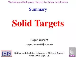
Tests on Tantalum Wire The wire lasted for a few hundred thousand pulses before breaking or bending. Tantalum is not a suitable material since it too weak at high temperatures (1600-2000 K).
Photograph of the tantalum wire showing characteristic wiggles before failure.
Ultimate Ultimate Yield Yield Ultimate Yield Yield and Ultimate Strength of Tantalum and alloys versus Temperature.
Yield Strength of Tungsten and some Alloys versus Temperature
Ultimate Tensile Strength, MPa Ultimate Tensile Strength of Tungsten and some Alloys versus Temperature
Tests on Tungsten Wire Tungsten is much stronger than Tantalum particularly at high temperatures. So - try Tungsten
Some Results: 0.5 mm diameter Tungsten Wires “Equivalent Target”: This shows the equivalent beam power (MW) and target radius (cm) in a real target for the same stress in the test wire. Assumes a parabolic beam distribution and 3 micro-pulses per macro-pulse of 20 micro-s.
W26 Broken Tungsten Wire after 13 million pulses.
W3 Tungsten Wire, after operating at 4900 A, peak temperature 1800 K, for 3.3x10⁶ pulses and then a few pulses at 7200 A at >2000 K.
W5 Tungsten Wire showing “wiggles”: 6200 A, >2000 K peak temperature, 5625 pulses.
Radiation Damage • Experience on the ISIS targets show that there is no serious problem up to ~12 dpa. • Tungsten pellets irradiated (~15-20 dpa) at PSI will be examined when cool enough.
Conclusions I believe that the viability of solid tungsten targets at high-temperaturefor a long life (~10 years) has been demonstrated with respect to thermal shock and fatigue and will not suffer undue radiation damage.
Future Programme • Continue wire tests with Tungsten and Graphite. • Continue modelling computations. • VISAR measurements to asses the properties of tungsten, and any changes, during the wire tests. (Effect of thermal shock.) • Tests with a proton beam to confirm wire tests and VISAR measurements – but limited number of pulses. • Radiation damage studies. • Test alloys of tungsten. • Design & build a model of the target bar system. • Design the solenoid. • Design and cost the complete target station including the beam dump.