Download
1 / 58
600 likes | 864 Views
Surface Flattening in Garment Design. Zhao Hongyan. Sep. 13, 2006. Surface Flattening. Application: aircraft industry ship industry shoe industry garment industry. 3D-Computer Aided Garment Design. 1. Import several patterns from other 2D garment CAD systems.

E N D
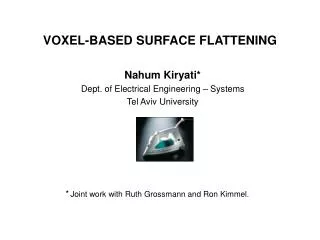
Surface Flattening in Garment Design Zhao Hongyan Sep. 13, 2006
Surface Flattening • Application: • aircraft industry • ship industry • shoe industry • garment industry
3D-Computer Aided Garment Design 1. Import several patterns from other 2D garment CAD systems. 2.Obtain 3D garment patterns after a sewing simulation process. 3. Modify the 3D garment patterns by FFD (free- form deformation) tools. 5. 2D comparison 4. Flatten the modified garment patterns.
3D-Computer Aided Garment Design It is important to flatten the modified garment patterns properly, as the modification is always done in the flattened surface in practice.
Problem Definition Given a 3D freefrom surface and the material properties, find its counterpart pattern in the plane and a mapping relationship between the two so that, when the 2D pattern is folded into the 3D surface, the amount of distortion—wrinkles and stretches—is minimized.
Measurement of accuracy • Area accuracy. A : the actual area of one patch on the surface before development; A’ : the area of its corresponding patch after development. A can be approximated by summing the area of each triangle in the facet model:
Measurement of accuracy • Shape accuracy. L : the actual length of a curve segment on the original surface before development; L’ : the corresponding edge length on the developed surface after development. L can be approximated by summing the length of each triangle edge in the facet model:
Planar parameterization • Floater 97’ • Fixing the boundary of the mesh onto a unit circle a unit square
Planar parameterization For interior mesh points: Forming a sparse linear system
Surface flattening based on energy model Charlie C.L. Wang, Shana S-F. Smith, Matthew M.F. YuenCAD 2002;34(11):823-833
Mass-spring systems ◆Ф is a planar triangular meshpair (K, P) ◆ A mass-spring system is established for the deforma-tion of Ф.
Mass-spring systems Elastic deformation energy function Tensile force
Discrete Lagrange Equation • Mass-spring system is governed by Discrete Lagrange Equation:
Discrete Lagrange Equation • ui is the mass value; • ri is the damping coefficient; • gi is the total internal force acting on vertex i, due to the spring connections to neighboring vertexj; • fi is the external force.
Surface flattening based on energy model • Initial triangle flattening • Planar mesh deformation
Surface flattening based on energy model • Initial triangle flattening • Planar mesh deformation
◆ Initial triangle flattening ◆ Assume one edge (Q1Q2) has already been flattened.
◆ Initial triangle flattening §2.1 Unconstrained triangle flattening ◆The third node (Q3) is going to be located on the flattened plan.
◆ Initial triangle flattening(2) §2.1 Unconstrained triangle flattening # Developable surface # Non-developable surface
◆ Initial triangle flattening(2) §2.2 Constrained triangle flattening Original mesh triangle Planar mesh triangle When two edges are both available to determine the planar point corresponding to Q3, the obtained two points, shown as P’3 and P’’3, may not be uniform.
◆ Initial triangle flattening(2.2) §2.2 Constrained triangle flattening In this case, a mean position is used
Surface flattening based on energy model • Initial triangle flattening • Planar mesh deformation
◆ Planar mesh deformation • Discrete Lagrange Equation can also be written in the following form: M: spring mass; D: damping matrix; K: stiffness matrix. Ignore the damping item
◆ Planar mesh deformation For each node Pi, the equation can be changed to mi: the mass of Pi ; ρ: the area density of the surface; qi(t): the position of Pi at time t; fi (t): the tensile force on node Pi;
◆ Planar mesh deformation • Penalty function Goal: to prevent an overlap
◆ Planar mesh deformation • the deformation process is described by the algorithm in the following
◆ Examples Example.2 a trimmed surface and its 2D Pattern Example.1 a ruled surface and its 2D pattern Table. 1 Calculation statistics of Example. 1 and Example 2
◆ Additional phase: Initial Energy Release • Since energy was generated in the first phase: Constrained triangle flattening, overlapping error would happen. Original 3D mesh surface Surface development without energy release
◆ Additional phase: Initial Energy Release • Therefore, the energy release is added
◆ Additional phase: Initial Energy Release Surface development without energy release Original 3D mesh surface Surface development with energy release
◆ Additional phase: Surface Cutting • Surface cutting • Some complex surfaces difficult to develop
◆ Additional phase: Surface Cutting • Surface cutting • Firstly, compute the energy on the developed surface.
◆ Additional phase: Surface Cutting • Surface cutting • Second, determine a reference cutting line using an elastic deformation energy distribution map.
Freeform surface flattening based on fitting a woven mesh model Charlie C.L. Wang, Kai Tang, Benjamin M.L. YeungCAD 2005;37(8):799-814
Woven mesh model • Planar woven fabric • Weft / warp springs: tensile-strain resistance • Diagonal springs: shear-strain resistance • NodeVi,j: intersection between springs
Woven mesh model: assumption • 1. The weft threads and the warp threads are not extendable. • 2. No slippage occurs at the crossing of a weft and a warp thread. • 3. A thread between two adjacent crossing is mapped to a geodesic curve segment on the 3D surface.
Woven mesh model: assumption • The directions of weft and warp springs are orthogonal to each other. • Users specify • Initial length of springs: rweft, rwarp.(rdiag) • Center Node: ViC,jC • Tendon node: Vi,j (i=ic, or j=jc) • Region node: otherwise. • Type-I/II/III/IV node
Basic idea • Fit a woven-like mesh (woven mesh) model onto a 3D surface M; • Map the surface point onto the plane.
Basic idea • Fit a woven-like mesh (woven mesh) model onto a 3D surface M; • Map the surface point onto the plane.
Fitting methodology • TNM (tendon node mapping) • DNM (diagonal node mapping) • Diffusion process
Fitting methodology • TNM (tendon node mapping) • DNM (diagonal node mapping) • Diffusion process
TNM • Specify a center point pC and a warp direction vector twarp on M. • Compute the weft direction vector tweft. • Call Algorithm ComputeDiscreteGeodesicPath(ViC,jC, twarp,M,rwarp). Iteratively until the boundary of M is reached. • Determine all the tendon nodes.
Fitting methodology • TNM (tendon node mapping) • DNM (diagonal node mapping) • Diffusion process
DNM • Four quadrants • For a type-I node Vi,j (1) AssumeVi-1,j-1, Vi-1,jandVi,j-1 all have been positioned; (2) Determine two unit vectors and ; (3) Set the diagonal direction as tdiag=1/2(t1+t2); (4) Staring at Vi-1,j-1, search the point on the geodesic path along the tdiag direction with distance rdiag, by calling Compute Geodesic algorithm iteratively;
(5) Locally adjust the position of Vi,j Strain energy release