Download
1 / 1
10 likes | 71 Views
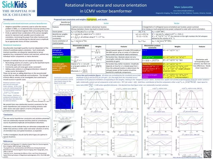
Marc Lalancette marc.lalancette@sickkids.ca Diagnostic Imaging, The Hospital for Sick Children, Toronto, Ontario, Canada. Rotational invariance and source orientation in LCMV vector beamformer. Introduction. Proposed new constraints and weights (highlighted), and results.

E N D
Marc Lalancette marc.lalancette@sickkids.caDiagnostic Imaging, The Hospital for Sick Children, Toronto, Ontario, Canada Rotational invariance and source orientation in LCMV vector beamformer Introduction Proposed new constraints and weights (highlighted), and results Linearly constrained minimum variance beamformer • Adaptive spatial filter commonly used to solve the inverse problem in MEG, i.e. to determine the neuronal activity at the source of the detected magnetic field surrounding the head. • Finds an optimal linear combination of the sensors (weights vector) to represent each possible source location and orientation, minimizing the power from other locations and orientations while maintaining the desired source amplitude by an appropriate choice of linear constraints. Rotational invariance • Any physically meaningful quantity must be independent of the choice of coordinate system orientation. Such rotationally invariant quantities can always be represented as tensor equations (e.g. composed of vectors and matrices), without any individual vector components or matrix elements. • Examples of methods that are not rotationally invariant: • Normalizing columns of a matrix, such as the lead field matrix in the array-gain vector constraint1; • Commonly used unit-noise-gain vector constraint1; • Adding scalar solutions in orthogonal directions instead of using a vector formulation2,3. • These can be seen as adding distortions in the reconstructed activity that can affect amplitude and localization. The strength of these effects remains to be investigated, but could lead to missed sources in specific cases. Source bias and resolution figures: All values are normalized by the simulated source field amplitude and for unit-gain. is the angle from the simulated source orientation to the physical orientation corresponding to the weights, rotating in the “tangential source” plane. Dashed lines: square root of total projected power (trace for vector solutions – right, rotationally variant sum of components and for scalar – left). Solid lines: contribution of the first component, either or . Input signal to noise ratio (SNR) 0.85 unless specified otherwise. Dot-dashed lines (last figure only): non rotationally-invariant solutions. Distributions of various system and source parameters used to chose typical values for bias figures on the right. Rotational variance in array-gain and unit-noise-gain vector solutions. As the x and y axes are rotated tangentially, the total projected amplitude (dashed lines) changes. Solid lines: x-component contribution: . (See bias figure description box for additional details.) , uniform noise, SNR=50 , uniform noise, SNR=50 , uniform noise , uniform noise We present here new rotationally invariant constraints for the vector beamformer and compare the resulting solutions with other vector and scalar options in terms of location and orientation bias and resolution. , full noise covariance , uniform noise , uniform noise , full noise covariance Conclusion • The new vector beamformer constraints and solutions presented here are rotationally invariant and thus avoid an unnecessary source of potential amplitude and localization distortions. • Preliminary results indicate they are otherwise comparable to or better than previous similar scalar and vector solutions in terms of orientation bias and spatial resolution, as expected. • Further investigation should clarify which types are optimal in typical situations. , uniform noise , SNR=100 , uniform noise, SNR=100 , 2 sources, uniform noise , 2 sources, uniform noise References 1Sekihara K and Nagarajan S S, Adaptive Spatial Filters for Electromagnetic Brain Imaging, 2008, Springer-Verlag, Berlin. 2Huang M-X et al., Commonalities and Differences Among Vectorized Beamformers in Electromagnetic Source Imaging, Brain Topography, 16:3, 2004, p 139-58 3Johnson S et al., Examining the Effects of One- and Three-Dimensional Spatial Filtering Analyses in Magnetoencephalography, 2011, PLoSONE 6(8): e22251. http://dx.doi.org/10.6084/m9.figshare.1148970