Download
1 / 27
270 likes | 394 Views
Improved Terrain Generation From UAV Sensors. Nascent Systems. Presented at MOVES Research and Education Summit July 12-14, 2011 NPS, Monterey CA. By Wolfgang Baer Associate Research Prof. Naval Postgraduate School Monterey, California Baer@nps.edu.

E N D
Improved Terrain Generation From UAV Sensors Nascent Systems Presented at MOVES Research and Education Summit July 12-14, 2011 NPS, Monterey CA By Wolfgang Baer Associate Research Prof. Naval Postgraduate School Monterey, California Baer@nps.edu
Improved Terrain Generation From UAV Sensors • Image-Model Feedback Algorithm for Rapid Terrain Database Generation • Dual eye input registration aid • Interactive Registration Algorithm • PVNT Mission Control Station • Image Registration Bottleneck • Dual Eye Input Experiments
Rapid Terrain Database Generation using the Image Feedback Algorithm Perspective View Generator Data Base Update Algorithm Difference Objective Data Bases update Measured Generate Products Raw Data Return Products Fig. 1. Block diagram of Model-Image Feedback Algorithm
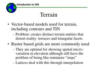
Advantage of Image-Model Feedback Algorithm • It is easier to generate accurate perspective views from 3D models than to perform pattern recognition on 2D images in order to generate 3D models. • Examples are • Shadow effects • Haze and atmospheric effects • Local feature heights • Foreshortening and perspective distortions
Importance of Shadows measured difference calculated target shadow Fig. 3. Shadow Example Comparisons from UAV flights during TNT 06-2
Atmospheric Effects Shadows And Haze No Shadow Shadow and Haze Effects Fig. 4. Shadow and surface haze correction in calculated PVNT reference images
Local Feature Heights Measured Difference Calculated Local feature heights are required both for shadow calculation and to avoid the flat look when comparing actual with oblique views generated from draped data bases such as Google Earth
Automatic Aspect Angle and Foreshortening Correction Reference Image Reference Image in Measured Image Perspective
TNT/CBE UAV Scenario Experimentation TNT experiments NPS / SOCOM at Camp Roberts Empire Challenge NPS/ China Lake
Ingest UAV Image Image and Telemetry To PVNT Work Station From UAV Operator selects Image
Calculate Reference Image UAV Image Calculate Reference Image Reference Image
Register Image When the Difference image is all yellow there is no error between the measured and calculated image If(Error> Lim) Re-Calculate Reference Image Reference Image
Automatic Ortho-rectification and Database Insertion Ray trace algorithm of Reference image stores x,y,z location of all image points so ortho-rectifiction and terrain database insertion is reduced to a lookup and image transfer function.
Image Registration Bottleneck Function Time • Image transmission and Ingest () • Reference image generation • Image Registration to 1 meter resolution • Ortho-rectification • Database storage Real time to 1sec/frame 10-30 Fps Several Seconds to Minutes 10-30 Fps 10-30 Fps
Automated Pixel Matching Method • Works well when images are radio-metrically identical and the only difference is the projection Calculated Measured Difference Before Difference After Registration Registration -74.19oh -21.19o -63.00oh -35.50op 11.19oh -14.31op -. 02op -.03op Fig. 9 Registration of Two Radiometrically Identical Images • Fails when measured and reference images differ due to environment, illumination, sensor modeling differences, database errors. • Registering different images is our problem.
Common Image points Projected ground control points p h Calculated Image r The classic Three or More Point Matching Method Automatically selecting common image points accurately can be difficult in unstructured open terrain.
Interactive method Still most reliable in an operational setting drag Fig. 8 Difference window with manual registration mouse commands
Interactive Camera Parameter Estimation • Traditional 3 control and 3 measured point entry is a 6 click batch process • Interactive Camera Parameter Estimation recalculates the best registration camera parameters after every entry • Potentially reduces entry of registration data to one click • Transferring Attention between two Images is fatiguing
Live UAV Image Input in one eye and calculated image in second eye Calculation control feedback Same? Correction Bi-scopic UAV image exploitation system setup
Live UAV Image Input in one eye and calculated image in second eye Calculation control feedback No Same? Correction Store in Database get next image Bi-scopic UAV image exploitation system setup
When Stereo effect is Reached Images merge And look 3D Calculation control feedback yes Same? Correction Store in Database get next image Bi-scopic UAV image exploitation system setup
Terrain Generation Experiment Conclusion • Automated image registration still requires human cognition for general open field applications • Interactive registration can utilize each measured and control point to improve registration and minimize data entry load • Dual –Eye input may provide a usefull interface for automated database insertion and UAV flight control
PVNT MCS Workstation Demo • Conducted at 6Pm • Watson Hall Rm 272 • Demonstrate • PVNT • Two Camp Roberts Interface Computers • Dual Eye Input display
Contact Information • Prof. Wolfgang Baer Dep. of Information Science Code IS, Naval Postgraduate School, 1 University Circle, Monterey, CA 93943, • Tel 831-656-2209 Baer@nps.edu Sponsors