Download
1 / 53
530 likes | 535 Views
Effect of Saline Condition on Coated & Non-Coated Pelton Turbine Buckets. Author: Dokiparti Satish Post Graduate Student, MED, SVNIT Co- Author’S : ( a) Gaurang C. Chaudhari ( b ) D r . s.a . channiwala

E N D
Effect of Saline Condition on Coated & Non-Coated Pelton Turbine Buckets Author: Dokiparti Satish Post Graduate Student, MED, SVNIT Co-Author’S: (a) Gaurang C. Chaudhari (b) Dr. s.a. channiwala Assistant Professor, Dept. Of Mechanical Engineering Professor CKPCET MED, SVNIT
India is currently the fifth largest electricity producer in the world. The electricity sector in India had an installed capacity of 223.625 GW as of April 2013. • According to India's Ministry of Power, about 14.1 GW of new thermal power plants under construction are expected to be put in use by December 2014, so are 2.1 GW capacity hydropower plants and a 1 GW capacity nuclear power plant. • With such a substantial amount of electrical energy being produced by Turbine generators, it is in the best interest of society to make these generators as efficient and as sustainable as possible. • To ensure the required fuel efficiency, reliability and ecological compatibility for modern and future turbines, researches have to solve the problem of high geometric accuracy (upto several hundredth of a millimeter) and a high surface quality of complex shaped blades made of corrosion resistant , high strength materials, wear resistance etc.
To study ageing mechanism causing degradation of a material. To study various reasons for the failure of materials during operating conditions. Finally to study Life enhancement method for different turbine blade material with Thermal Spraying techniques. To carry out experiments and analysis for enhancing the erosion resistance of pelton turbine buckets by ceramic coatings using plasma spray coating method.
The purpose of life extension activities is not to continue the operation of power plant beyond its useful life, But merely to ensure full utilization upto its Useful life. • A key ingredient in life extension is RLA(Remaining life Assessments) Technology . • A Material is traditionally built for a Finite design life; since their both deformation and fracture are time dependent. As long as the operating stress do not exceed the design stress, these components, in principle, should serve indefinitely. • BUT IN PRACTICE VARIOUS FACTORS CAUSE REDUCTION IN THEIR LIFE AND REULTS IN THE FAILURE.
CREEP - Progressive deformation of the material at steady temperature and pressure. It occurs as a result of long term exposure to high levels of stress that are below the yield strength of the material FATIGUE - It is the progressive and localized structural damage that occurs when a material is subjected to cyclic loading. CORROSION - It is the gradual destruction of material, usually metals, by chemical reaction with its environment. (Kirkendall effect, emf, electrolysis ) WEAR -Removal and deformation of material on a surface as a result of mechanical action of the opposite surface EROSION - Erosion is a Cavitations wear, where the erosive medium or counter-body is a fluid FRETTING – Itrefers to wear and sometimes corrosion damage at the asperities of contact surfaces. This damage is induced under load and in the presence of repeated relative surface motion, as induced for example by vibration.
Shot Peening Process : Shot peening is a cold working process used to produce a compressive residual stress layer and modify mechanical properties of metals. It entails impacting a surface with shot (round metallic, glass, or ceramic particles) with force sufficient to create plastic deformation. Tensile stresses attempt to stretch or pull the surface apart and may eventually lead to crack initiation. Compressive stress squeezes the surface grain boundaries together and will significantly delay the initiation of fatigue cracking. Shot peening is the most economical and practical method of ensuring surface residual compressive stresses. In power plant, generally Turbine blades are checked for defects using Non Destructive Testing methods like Ultrasonic Testing after every 3500 operational hrs and if no defects are detected then after every 50,000 operational hrs Blades are Shot peened to increase its operational Design life.
b. Application of Coatings on Material using Thermal Spraying : • In all sectors of industry today, the catch phrase “better, faster, cheaper” is common and valid, as it seems that production demands are ever-increasing. • If this service life is deemed unacceptable, either the entire component must be made of a more wear resistant material, or the area where the wear occurs must be protected. For cost reasons, the usual decision is the latter. • This leads to the use of surface coatings. Either the entire component can be coated or just the area prone to attack, whichever best fulfills the requirements • Hence, Spray and Fuse coatings have established an excellent track-record of corrosion, erosion, wear etc. or one of the best economical methods for life enhancement of power plant components for a wide range of environments. Fig - completely worn pelton turbine nozzle needle Fig – Premature losses on Gas Turbine Blade
It is a group of coating processes in which finely divided metallic or non-metallic materials are deposited in a molten or semi molten condition to form a coating. The coating material may be in the form of powder, ceramic-rod, wire or molten materials Basic Principle of thermal spraying Coatings on Turbine Blades
Based upon the two heat source a “family tree” of thermal spray methods can be converted into :
Many hydro electric project sites in India face severe silt erosion problems in turbines which over a period of time drastically reduces the overall efficiency of power generation system. • Erosive wear of hydro turbine runners depends upon different parameters such as size, hardness and concentration of silt particles, velocity of flow, properties of the base material of the turbine components and operating hours of the turbine. • The mechanism of erosion in general may be discussed as follows. When particles strike the surface at small impingement angle the material is removed by cutting mechanism. The abrasive grits roll or slide when they strike on the surface at small impingement angle and cause erosion by abrasion or cutting mechanism.
Wear and Erosion Testing Standards and Practices : The ASME / ASTM Committee on Wear and Erosion recommended various standard test procedures for wear testing. But none among these standards meet the requirement of the slit laden water impingement erosion conditions similar to Indian and Chinese hydro turbine conditions. Vibrating Cavitation Test ( ASTM G32-77) This method covers the determination of rate of cavitation erosion that is due to generation of cavitation bubbles which collapse on face of specimen vibrating at high frequency. Further the test condition in this standards are as the temperature control at 22 ± 10 OC , use of distilled water, gas or air required at pressure 96 ±12 KPa and displacement peak to peak in water 0.051 ± 5 % mm throughout the test The mechanism of slit impingement erosion and vibratory cavitation erosion are totally different
Abrasion Test (ASTM G 65 – 80 ) This practice covers laboratory procedure for determining the resistance to metallic material to scratching abrasion by means of the dry sand rubber wheel During this test temperature rises and hence does not match the hydro turbine conditions. Further in this test, no where water is involved. Liquid Impingement Erosion Test ( ASTM G73 – 82) This practice concerns the test in which solid specimen are eroded by repeated impacts of liquid drops or jets. This practice is not applicable for predicting the erosion resistance of material due to solid particles corrosive impingement or due to continuous high velocity liquid jet aimed at a surface.
Solid Particle Impingement Erosion Test (ASTM G73 – 83) This test covers the determination of material loss by jet of gas entrained solid particle impingement erosion with jet nozzle type erosion equipment. In this test, actual erosion service involves particle size, velocity, angle of impingement and environment This testing method does not have any simulation with the hydro turbine site condition and hence do not suit the requirement of slit laden water erosion test.
Design of Slit – Water Impingement Erosion Testing Rig • Slit – Water Impingement Erosion Testing Rig unit has five main parts: (a) Slit control unit, (b) Slit water mixing nozzle, (c) Erosion chamber, (d) Filtering unit and (e) Water pumping unit.
(a) Design of Nozzle Existing Pumps specification : Head – 27 m Discharge – 1.16 lps N – 2880 rpm Outlet pipe diameter – 3.5 cm Velocity of water (V) = CV Mass Flow rate of water ( m ) = ρ A V = 0.78 1.16 = 1000 x A x 18 = 17.9525 A = 6.44 x 10 -5 m2 = 18 m/sec = 6.44 x 10 -5 m2 Therefore, Jet Dia = 9.06 mm 9 mm. Hence, a Convergent type Nozzle was designed according to jet dia (9 mm) and pipe dia (35 mm)
(b) Dimensions of Pelton Bucket Dimension of pelton buckets were as shown in Figure :
(c) Material Selection of Nozzle W.P.S Material was selected for the fabrication of nozzle. WPS is a tradename of W. Ossenberg & Cie. for Werkstoff Number 1.2713 cold work tool steel. It contains nickel (1.65 %), chromium (0.70 %), carbon (0.55 %), silicon ( 0.25 %), manganese (0.80 %) and molybdenum (0.10 %) in weight, for a good combination of toughness and hardenability. Further to enhance its strength it was harden at a temperature of 830 – 870 OC followed by oil quenching. Hardness after quenching was 56 HRC.
An experimental setup was designed and fabricated to carry out the required investigation. Figure shows a schematic of the test setup consisting of: (a) Collecting tank; (b) Pelton turbine runner; (c) nozzle; (d) Silt control unit; (e) silt control valve; (f) orifice plate; (g) main control valve; (h) by-pass circuit; (i) by-pass control valve; (j) water pumping unit; (k) water supply tank.
The Pelton turbine runner having 18 buckets ( i.e. 5 casted buckets, 10 buckets with hardened process after casting and remaining 3 buckets coated with ceramic coating) with pitch circle diameter of 250 mm and nozzle diameter of 9 mm. • In order to get measurable amount of erosion in short period of time, the turbine buckets were made of LM 25 Aluminium Casting Alloy (Al – Si7Mg); this alloy conforms to British Standard 1490 LM25. The weight of each blade was in the range of 150- 200 g.
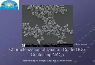
Selection of Coating Powder and Spray Method for Erosion Protection of Pelton Buckets Ceramic materials are known for their significant resistance against wear and corrosion. However, the high cost of production and brittle nature associated with ceramic material components, restrict the use of ceramics as bulk materials to a great extent. Due to these reasons, ceramic coatings are applied on to the components made of materials like steel, which are cheaper and shock resistant, to enhance their resistance against wear and corrosion. Such coatings are usually applied by thermal spray technologies. Hence Ceramic coating of Al2O3 (60%) and TiO2 (40%) was applied on Pelton buckets using Plasma Spray coating method as shown in Figure
Process Parameters of Plasma Spray for Ceramic coatings on Pelton Buckets
Experimental Procedure : 1. Initial Weights of Pelton Buckets
Formation of Aluminum oxide on buckets surface On coated bucket On Hardened bucket On non coated, non hardened bucket
BUCKET -1 ( with coating ) SEM RESULTS ( Surface Morphology) (Porosity)
SEM RESULTS BUCKET -5 ( without coating and hardened ) ( Surface Morphology)
BUCKET - 6 ( Hardened) SEM RESULTS ( Surface Morphology) (Porosity)
BUCKET - 8 ( Hardened) SEM RESULTS ( Surface Morphology) (Porosity)
BUCKET - 10 ( Hardened) SEM RESULTS ( Surface Morphology) (Porosity)
BUCKET - 12 ( Hardened) SEM RESULTS ( Surface Morphology) (Porosity)
BUCKET - 14 ( Hardened) SEM RESULTS ( Surface Morphology) (Porosity)
BUCKET - 17 ( with Coating) SEM RESULTS ( Surface Morphology) (Porosity)
Hardness of the working fluid plays a vital role in life enhancement of material. • Scaling tends, to be the result of water with a high hardness. • Hard water typically contains a lot of calcium / chlorides compounds which can precipitate out as calcium carbonate chlorites which results in pitting type of corrosion. • Since porosity increases the oxidation of the material, thus selection of fabrication process is a key factor in predicting the life of a material. • The experimental result may be useful for turbine manufacturing industry in order to predict the quantum of erosion in Pelton turbine bucket at manufacturing stage and for life enhancement of pelton buckets according to working condition and environment. • In nutshell, it may be stated that the development of an innovative test rig for erosion of pelton wheel bucket forms an important outcome of present work. Further the evidence of oxidation due to porosity in material highlights a need for better forming and coating method for pelton wheel buckets to enhancement of its life
In the future work different alloy materials can be taken for this study and variables like hardness, sharpness, impact angle, silt concentration etc. can be a variable to simulate the actual flow conditions and actual phenomenon of erosive wear can be studied. • Different type of ceramic coatings likes Chromium oxide (Cr2O3) with better sealant can be used • Testing Rig can be further used for erosion testing of other types of equipments like slurry and mud pump impellers • Can also be used for testing of Micro Turbines. • To avoid corrosion attack, materials like stainless steel (grade SS 316) can be used instead of Mild Steel and Cast Iron. • Casing of the testing impeller should be completely sealed from the surrounding atmosphere to avoid the attack of oxidation and corrosion on the material. • The experimental results about the effect of saline condition or hard water on pelton turbine buckets can be very useful for turbine manufacturing industry especially for coastline areas
All India Regionwise Generating Installed Capacity of Power, Central Electricity Authority, Ministry of Power, Government of India, (2013). http://www.renewindians.com/2012/12/Renewable-energy-contribution-in-india.html Get enlightened about electricity – India , The Financial Express, (2004). Power sector at a glance: All India data, Ministry of Power, Government of India, (2012). World Coal Institute – India, The coal resource, a comprehensive overview of coal, World Coal Institute, (2009). India: Overview, Data & Analysis, U.S. Energy Information Administration, (2011). For India, a Power Failure Looms, The Wall Street Journal (2012). Technology development prospects for the Indian power sector, International Energy Agency France, OECD (2011). Load Generation and Balance Report, Central Electricity Authority, Ministry of Power, Government of India, (2012). Remaining Life Assessment reports, Turbo Metallurgical services ltd., Hyderabad, (2011).