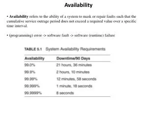
Download
1 / 81
810 likes | 1.21k Views
SATCOM Availability Analysis. ICAO Working Group M Iridium Subgroup. August 23, 2006. Background.

E N D
SATCOM Availability Analysis ICAO Working Group M Iridium Subgroup August 23, 2006
Background • This briefing describes work supporting NASA, the FAA and EUROCONTROL to develop technology evaluation criteria for evaluation of new technologies for mobile aeronautical communications as part of the FCS • The technology assessment team was charged to “investigate new terrestrial and satellite-based technologies” • The technologies that are recommended must: • Meet the needs of aviation (as identified in the COCR and ICAO consensus documents) • Be technically proven • Be consistent with the requirements for safety • Be cost beneficial • Promote global harmonization
SATCOM Task Activity Overview • The purpose of this task was to assess the viability of using existing commercial satellite systems with AMS(R)S frequency allocations to provision the communications services that are detailed in the COCR • Task Activities • SATCOM Availability Analysis • Provide a comparative analysis of the availability of identified commercial satellite architectures and a VHF terrestrial communication architecture for provision of aeronautical mobile services • COCR Service Provisioning Using SATCOM & Hybrid Architectures • Determines if SATCOM technology candidates can meet COCR requirements • This briefing only covers COCR Service Provisioning Using SATCOM Architectures
Comparative Analysis • The following tasks were performed for this comparative availability analysis: • Identify/describe architectures for analysis • Define availability, assumptions and analysis approach • Calculate and analyze availability contributors • Compare/discuss analysis results
Identify Architectures for Analysis • Two satellite service architectures with AMS(R)S frequency allocations were identified for consideration in this analysis • Inmarsat-4 SwiftBroadband (SBB) service • Iridium communication service • These architectures were contrasted with a generic VHF terrestrial communication architecture • Data communications architecture based on existing infrastructure
Identify Architectures for Analysis: Inmarsat SBB (3) • Representative Inmarsat SBB NAS coverage area • Example reference area is covered by three SBB spot beams within the Inmarsat I-4 satellite coverage area • Spot beam coverage for this area is illustrated below
Identify Architectures for Analysis: Iridium (2) • Representative Iridium coverage area • Example Iridium reference area falls within 2 orbital planes • Approximately 20% of this area falls within view of two orbital planes ORBITAL PLANE 1 ORBITAL PLANE 2
Identify Architectures for Analysis: Terrestrial (2) • Representative coverage area • The analyzed terrestrial architecture assumed a redundancy scheme loosely based on current RCAG/BUEC redundancy • For portions of the reference area, BUEC sites providing RCAG/BUEC redundancy are shown • Figure illustrates coverage density with significant overlap; for analyzed architecture, minimal overlap was assumed • Credit for significant redundancy in current A/G voice architecture was not taken • Assumed that a unique RCAG/BUEC redundant pair provides area coverage in the analyzed terrestrial architecture
(Observation Time – Total Outage Time) Observation Time Definitions, Assumptions and Approach • Availability • Given that link interruptions and system component failures can lead to service outages, and each outage requires varying restoration times, availability characterizes the impact of interruptions, failures and service restoration times on the usability of a system • Percentage of the time a system is available for use • Generally described as the following ratio: • To apply the ratio above, a definition of ‘Outage Time’ is needed • Typically, an outage is defined as the time the service is not meeting a specified performance or Quality of Service • For data service, this is often described as a service providing a certain bit error rate (BER) while meeting maximum latencies
Definitions, Assumptions and Approach (2) • RTCA DO-270, MASPS for the AMS(R)S as Used in Aeronautical Data Links, considers two categories of outages • Multi-User Service Outage: A Service Outage simultaneously affecting multiple aircraft within a defined service volume • Single-User Service Outage: A Service Outage affecting any single user aircraft within a defined service volume • Focus for this analysis is service provisioning for multiple aircraft within a defined service volume • Consideration of outages is ‘multi-user service outages’
Note: TOBS = Observation Time TOUT = Outage Duration X = Observation Location Px(x) = Probability density function of users over the coverage volume Ω Definitions, Assumptions and Approach (3) • Geographically Dependent Availability Ratio • If a system covers a large region of airspace and if partial outages could occur, then a geographically dependent availability ratio should be used • This was applied in some cases of the current analysis
Communications Unavailable for >TOD System Component Failures Fault-Free Rare Events OR OR Ground Station Equipment Failure Event RF Link Event Satellite Control Equipment Failure Event Capacity Overlaod Event Interference Event Aircraft Station Failure Event Scintillation Event Satellite Failure Event Definitions, Assumptions and Approach (4) • Approach • Utilized SATCOM availability analysis model described in RTCA DO-270 • Defines availability fault-tree to permit individual characterization and evaluation of multiple availability elements • Organized into two major categories • System Component Failures • Fault-Free Rare Events • Model is useful for comparing architectures and was used for this study
Definitions, Assumptions and Approach (5) • Approach (cont’d) • When a complex system consists of independent serial elements, the overall availability is equal to the product of the availability ratios for the individual elements: • This can be applied to the availability tree model to characterize an architecture availability with a single number and is the approach presented in DO-270 • However; this approach has its limitations • The independence assumption is not always valid • Reducing this complex model into a single number oversimplifies the issue • “Tall poles in the tent” in a multiplicative relation dominate the entire product • Operating Time (or Observation Time) periods may be different for different elements • This approach is risky when one or more of the element availability calculations are based on incomplete or unavailable data, as in this case • Due to these limitations, this approach was not used for this study AoSYS = Ao1 x Ao2 x Ao3 x … x AoN
Definitions, Assumptions and Approach (6) • Methodology used for this task • First, availability was assessed for each availability element for each of the three architectures • System component availability elements • Fault-free event availability elements • These findings were then compared and contrasted for each of the three architectures (SATCOM and terrestrial) • Compared estimated availability performance (terrestrial vs. SATCOM) • Identified outage impact for terrestrial vs. SATCOM systems
Definitions, Assumptions and Approach (7) • System Component Failure Availability Elements • Ground Station Equipment Failure Event • For Satellite Systems, failure events associated with the Ground Earth Station (GES) or stations and any terrestrial networking between the GESs (if there are more than one) • For terrestrial VHF radio, failure events associated with the ground radios and radio control equipment at the radio sites • Satellite Control Equipment Failure Event • For Satellite Systems, failure events associated with the Network Operations Center (NOC) • Not applicable to terrestrial architecture • Aircraft Station Equipment Failure Event • For both satellite and terrestrial VHF radio, failure events associated with aircraft radio equipment • Satellite Equipment Failure Event • For satellite systems, failure events associated with the satellite (for communication relay) • Not applicable to terrestrial architecture
Definitions, Assumptions and Approach (8) • Fault-Free Event Availability Elements • RF Link Event • For both satellite and terrestrial communication systems, accounts for random radio frequency events (such as severe fading) for which defined system link budgets are not met and which could lead to service outage • Capacity Overload Event • For both satellite and terrestrial communication systems, accounts for conditions where available communications capacity is overloaded • Interference Event • Accounts for aggregated interference environmental effects from external sources that may lead to service outage • For satellite systems, emissions from other SATCOM communication systems operating from other aircraft in the same operating space • For terrestrial systems, emissions from aircraft in the same operating space • Scintillation Event • Accounts for ionospheric events involving the sun and the earth’s magnetic field, which produce random variations in electromagnetic waves traversing the ionosphere • For this analysis, scintillation only applies to satellite communication systems (not relevant to VHF communications propagation effects)
Communications Unavailable for >TOD System Component Failures Fault-Free Rare Events OR OR Ground Station Equipment Failure Event RF Link Event Satellite Control Equipment Failure Event Capacity Overlaod Event Interference Event Aircraft Station Failure Event Scintillation Event Satellite Failure Event Calculate and Analyze Availability: System Components • System component availability calculations were based on FRS component failure model elements: • Ground Station Equipment • Satellite Control Equipment • Aircraft Station Equipment • Satellite Equipment
B C A D E Future Radio System (FRS) Calculate and Analyze Availability: Modeling the FRS Standard AMSS Model Block Diagram • For the two SATCOM systems, the Future Radio System (FRS) includes system components encompassed by Points B through C, as shown in the standard Aeronautical Mobile Satellite System (AMSS) model
Inmarsat SAS User Telecom Aircraft Earth Station (AES) Inmarsat I-4 Satellite User Control Site Equipment/Applications User Applications Inmarsat Data Comm WAN Inmarsat NOC User Telecom Inmarsat SAS Modeled Inmarsat FRS Calculate and Analyze Availability: Inmarsat SBB • Modeled Inmarsat architecture • General architecture assumptions • NAS is serviced by a single I-4 satellite with ground spare available for backup in the case of unrecoverable spacecraft failure • Users can be accommodated by either SAS • Inmarsat offers a fully redundant Network Operations Center (NOC)
Iridium NOC Iridium NOC Calculate and Analyze Availability: Iridium • Modeled Iridium architecture • General architecture assumptions • NAS is serviced by one or two Iridium orbital planes • Iridium offers a fully redundant NOC Modeled Iridium FRS User Telecom Aircraft Earth Station (AES) Aeronautical Gateway User Control Site Equipment/Applications Iridium Satellite Constellation User Applications User Telecom Iridium OSN
Primary Remote A/G Radios User Telecom User Control Site Equipment/Applications User Applications Aircraft Radio Backup Remote A/G Radios User Telecom Modeled Terrestrial FRS Calculate and Analyze Availability: VHF Terrestrial • Modeled VHF Terrestrial Architecture • Includes primary/backup radio redundancy • General architecture assumptions • Primary radios are configured with redundancy equivalent to current Remote Communication A/G (RCAG) sites • Backup radios are configured with redundancy equivalent to current BackUp Emergency Communication (BUEC) A/G sites
Inmarsat SAS Aircraft Earth Station (AES) Inmarsat I-4 Satellite Inmarsat Data Comm WAN Inmarsat NOC Primary Remote A/G Radios Aircraft Radio Iridium NOC Iridium NOC Inmarsat SAS Backup Remote A/G Radios Modeled Inmarsat FRS Modeled Terrestrial FRS Calculate and Analyze Availability: Ground Station • Ground Station components modeled for availability calculation Modeled Iridium FRS Aircraft Earth Station (AES) Aeronautical Gateway Iridium Satellite Constellation Iridium OSN
Calculate and Analyze Availability: Ground Station (2) • Ground Station Equipment Availability • SATCOM: Specific ground system outage information was not available from Inmarsat or Iridium • Instead, available GES outage information was used to derive ‘similar in kind’ assumptions applied to both Inmarsat and Iridium GES availability calculations • Terrestrial: Availability values associated with individual components were calculated based on published MTBF/MTTR values for existing NAS radio equipment (e.g. for RCAGs/ BUECs) • Reference NEXCOM SRD, Appendix E
Calculated availability values: Calculate and Analyze Availability: Ground Station (3) Ground Station Equipment Inmarsat Gnd Stn: Availability: essentially 1for yearly observation for all coverage volumes Iridium Gnd Stn: Availability: 0.99997 for yearly observation for all coverage volumes VHF Terrestrial Gnd Stn Equip Availability: 0.99999 for yearly observation for all coverage volume • Inmarsat offers very high availability ground systemsfor the entire service volume • Due to lack of ground station redundancy, Iridium ground station availability is not quite as high • For VHF terrestrial ground systems, this result is the system component availability
Inmarsat SAS Aircraft Earth Station (AES) Inmarsat I-4 Satellite Inmarsat Data Comm WAN Inmarsat NOC Inmarsat NOC Inmarsat SAS Modeled Inmarsat FRS Iridium NOC Iridium NOC Calculate and Analyze Availability: Ground Control Equipment • Satellite Ground Control Equipment modeled for availability calculation Primary Remote A/G Radios Aircraft Radio Backup Remote A/G Radios Modeled Iridium FRS Modeled Terrestrial FRS Aircraft Earth Station (AES) Aeronautical Gateway Iridium Satellite Constellation This element is not applicable to the Terrestrial Architecture Iridium OSN
Calculate and Analyze Availability: Ground Control Equipment (2) • Satellite Ground Control Equipment Availability • Both Inmarsat and Iridium offer fully redundant NOCs • For both Inmarsat SBB and Iridium, all users were assumed to be normally serviced by a single NOC • Specific satellite ground control equipment outage information was not available from Inmarsat or Iridium • Instead, review of available Ground Control outage information was used to derive ‘similar in kind’ assumptions applied to both Inmarsat and Iridium Ground Control availability calculations • Upon investigation of ground control station outages, it was difficult to find much outage information; however trends point to highly reliable ground control stations
Calculate and Analyze Availability: Ground Control Equipment (3) • Calculated availability values: Satellite Ground Control Equipment Inmarsat Ground Control: Availability: essentially 1 for yearly observation for all coverage volume Iridium Ground Control: Availability: essentially 1 for yearly observation for all coverage volume VHF Terrestrial Ground Control Not Applicable • Both Inmarsat and Iridium offer very high availability ground control systems for the entire service volume
Calculate and Analyze Availability: Aircraft Station • Aircraft Earth Station Equipment • For both satellite system and terrestrial VHF communications, the aircraft station equipment is highly dependent on the installation • For multi-user availability calculations, the focus is on service provisioning rather than on connectivity to an individual user • For multi-user availability calculations, aircraft station equipment availability is considered to be one (1) • This is consistent with the approach presented in DO-270 • Failures in aircraft station equipment that are dependent on installation, local interference effects for the aircraft, etc. are not accounted for; rather focus is on whether the user population in an associated service volume is accommodated in general
Calculate and Analyze Availability: Spacecraft • SATCOM Spacecraft Equipment • SATCOM • For SATCOM, the spacecraft equipment element includes the space segment components • For the Inmarsat SBB architecture, this addresses the single I-4 satellite that would provide SBB service to the NAS • For Iridium, this includes all satellites (including crosslinks) in the one or two orbital planes that would provide communication service to NAS coverage areas • Terrestrial VHF Communications • This component is not applicable to the terrestrial VHF architecture
Calculate and Analyze Availability: Spacecraft (2) • SATCOM Spacecraft Equipment Availability • Satellite failure information from Inmarsat and Iridium was not available for this study • To derive outage rates and durations for individual satellite availability contributors, historical satellite failure anomaly/outage information was reviewed to apply “similar in kind” statistics • Sources included: • “Satellite G&C Anomaly Trends”, Brent Robertson & Eric Stoneking, NASA AAS 03-071 • General satellite failure information fromhttp://www.sat-index.com/failures/index.html?http://www.sat-index.com/failures/echo4.html • NAVY GEOSAT Follow-On (GFO) detailed satellite event log • “Historical and Recent Solar Activity and Geomagnetic Storms Affecting Spacecraft Operations”, Joe H Allen, SCOSTEP, GOMAC 2002 • “Spacecraft Anomalies and Lifetime” by Charles Bloomquist of Planning Research Corporation • Satellite Insurance Rates on the Rise: Market Correction or Overreaction, Futron Corporation, July 10, 2002 • Informal Iridium tracking site: http://www.rod.sladen.org.uk/iridium.htm
Calculate and Analyze Availability: Spacecraft (3) • SATCOM Spacecraft Equipment • Considerations for SATCOM architectures • Two categories of spacecraft components were considered to contribute to individual satellite outages • Platform – comprises the following individual elements • Electrical Power System • Attitude Control System • Mechanical • Propulsion • Command & Data Handling • Communications • Software • Operations • Payload - includes component failures and software anomalies associated with payload equipment • Categories in red were the major Mean Time to Replace (MTTR) recoverable outage contributors
1 = 1 – [ ( ) ({SPk rec (TOut)k} + {PTot TOut Tot}) ] TObs k Calculate and Analyze Availability: Spacecraft (4) • Inmarsat Spacecraft Equipment Availability • Availability was calculated using historical satellite failure anomaly/outage information and the following relation : • Where: • TObs = Observation time = assumed mission life = 10 years • Pkrec = Probability of recoverable failure for kth equipment element • (Tout)k = Outage time associated with failure and recovery of kth equipment element • PTot = Combined probability of total (unrecoverable) equipment failure (1%) based on industry bus failure statistics and reasonable assumptions • TOutTot = Outage due to total failure = time to replace (relaunch/orbit) spacecraft = estimated 3 months
Calculate and Analyze Availability: Spacecraft (5) • Iridium Spacecraft Equipment Availability • Iridium spacecraft availability was calculated based on the assumption that the constellation serving the area under analysis is composed of one or two orbital planes each comprised of 11 satellites • Calculated using a geographic dependent availability formula • Assumed a two region model: in one region the reference area is serviced by a single orbital plane, and in the second region the reference area is serviced by two orbital planes • Because the Iridium architecture utilizes satellite crosslinks as part of the service chain, one crosslink was included in the service chain for the area under analysis • It was assumed that a satellite outage affects only the spotbeam associated with the satellite experiencing the outage (e.g. any crosslinks it had accommodated would be routed through neighboring satellites)
Calculate and Analyze Availability: Spacecraft (6) • Iridium Spacecraft Equipment Availability (cont’d) • The availability observation period for Iridium was set to the median design lifetime, or 6.5 years • The anomaly incident rate, approximately 12%, defined in the NASA study for LEO systems was assumed • For total failure recovery time, the outage time (time to move in-orbit spare into place) was taken to be 10 days • For orbital plane recoverable satellite failures, two approaches were employed • Approach 1: Use a set of recoverable failures identified in the NASA study* • Approach 2: Assume recoverable satellite anomalies are primarily due to weekly scheduled maintenance lasting up to 3 hours** and assumed to affect all satellites in an orbit simultaneously *Satellite G&C Anomaly Trends”, Brent Robertson & Eric Stoneking, NASA AAS 03-071 * *Described in the Iridium Implementation Manual, IRD-SWG03-WP06, 2-15-06, p. 46.
Calculate and Analyze Availability: Spacecraft (7) Satellite Equipment • Calculated availability values: VHF Terrestrial: Not Applicable Iridium Satellite: Average Availability/Mission Life: Approach 1: 0.9995 Approach 2: 0.99 Geographically dependent on one or two orbital plane coverage Inmarsat Satellite: Average Availability/ Mission Life: 0.9999 for all airspace • Spacecraft availability calculation issues • Straight-forward availability calculation results are difficult to apply • Spacecraft tend to be engineered for very high reliability due to inability to perform repairs • Long MTTR are typically the drivers in the availability calculations
Communications Unavailable for >TOD System Component Failures Fault-Free Rare Events OR OR Ground Station Equipment Failure Event RF Link Event Satellite Control Equipment Failure Event Capacity Overlaod Event Interference Event Aircraft Station Failure Event Scintillation Event Satellite Failure Event Calculate and Analyze Availability: Fault-Free Rare Events • Fault-Free Rare Events consist of communications outages due to statistically unlikely events not associated with any system failure mode • Fault-Free Rare Event availability calculations include: • RF Link Event • Capacity Overload Event • Interference Event • Scintillation
Calculate and Analyze Availability: RF Link Events • RF system link availability can be defined as: • Where ∑(TOUT)k is the total interval of time within the observation interval when the RF system link is not available for use • “Available for use" means that the RF link is capable of providing communications with the specified level of integrity while meeting the maximum transfer delay permitted by the operational application. • Typically the integrity parameter for RF digital links is bit error rate (BER)
Calculate and Analyze Availability: RF Link Events (2) • Satellite system design allows for outage events that: • Have a very low probability • Are not precluded by elements of the system design • Will occasionally occur even when the system is operating within its specifications. • In DO-270 Appendix B, RF link system performance is based on the parameter, , which is the probability that the RF link satisfies the link budget by providing the necessary C/N to meet the BER integrity requirement • Thus, if the performance is observed by sampling the RF link, with each sample defined as an event, then some fraction, 1−, of all events will not satisfy the link budget • Typically, is a design parameter, not an inherent characterization of the satellite link performance • The satellite service provider determines what level of availability it seeks to provide and then selects its hardware operating parameters to provide enough link margin to mitigate against random link and RF component degradations
Calculate and Analyze Availability: RF Link Events (3) • In Appendix B of DO-270, the pro forma RF link budgets include margin MC necessary to meet the specified availability () while accommodating typical random losses associated with satellite links, including the following: • Atmospheric Absorption Losses • Degradation of G/T from the Sun • Precipitation Loss • Satellite Antenna Variations • Satellite Hardware Variations • LNA Noise Figure Variations • Polarization Coupling Losses • Satellite Modulation Imperfections • Scintillation Loss • Because aeronautical SATCOM links are typically modeled as Rician fading multipath channels, the DO-270 pro forma RF link budgets accommodate fading losses with a Rician fading margin value
Calculate and Analyze Availability: RF Link Events (4) • As indicated in the previous slide, SATCOM link availability for a specific SATCOM system is highly dependent on numerous system-specific parameter values. • For the most part, these parameter values are not readily available from Inmarsat and Iridium • However, some link availability design goals for these two systems have been presented in technical studies • According to the Eurocontrol AeroBGAN Study: A “95% link availability, under all worst-case link conditions is the link design criterion” for Inmarsat IV. This is based on a minimum 5 degree elevation angle. • As yet, Iridium is “silent” on stated availability in the February 2006 draft of the Iridium Tech Manual for ICAO, though earlier studies state a link availability of 99.5% at the stated user data rate of 2400 bps, with a packet error rate of 10-6
Calculate and Analyze Availability: RF Link Events (5) • Further observations of SATCOM service RF link availability • As a point of comparison, DO-270 specifies multi-year availability of at least 0.993 over an Observation Time of one year • Inmarsat SBB service has not been in operation long enough for the vendor to gather sufficient RF link availability statistics • The broad range in operating parameters of SBB (e.g. data rate and transmit power) provides Inmarsat with significant latitude in providing specific levels of RF link availability • RF link availability is driven more by business considerations than technical considerations (e.g., the relatively small percentage of Inmarsat business represented by aeronautical services) • Iridium probably has less latitude in providing a broad range of RF link availabilities • Relatively fixed system design based on original Motorola Iridium design and operating parameters (e.g., its limited data rate and data rate range)
Calculate and Analyze Availability: RF Link Events (6) • Terrestrial VHF link availability • DO-224B notes that [italics added]: “the service availability goal of the end-to-end communication system” for data service is 0.999 (Section 2.4.1) • Observation Time is not specified
Calculate and Analyze Availability: RF Link Events (7) RF Link Event • As an operating parameter of a turnkey system, SATCOM system availability is predominantly under the control of the service provider and driven by business rather than technical considerations • With no definitive SATCOM service availability specified by the vendors for aeronautical A/G ATC data communications, this parameter is very limited as a useful quantitative criteria for comparison • Presumed availability values: Inmarsat RF Link: Availability: 0.95 (design criterion) Observation Time is not specified Iridium RF Link: Availability: 0.995 (as advertised by 1st generation operator) Observation Time is not specified VHF Terrestrial RF Link Availability: 0.999 Observation Time is not specified
Calculate and Analyze Availability: Capacity Overload Event • This factor accounts for the probability that a system can be overloaded by aeronautical services • This study implemented both a simple Erlang-B Model and a finite source Erlang-C model following DO-270 methodology and key assumptions • Focus was on En Route domain • Applicable domain for satellite service • Highest data rate required per user • Erlang-B (Blocked Calls Cleared) • Services requests are processed immediately or dropped immediately • No queuing • More pessimistic estimate • Erlang-C (Blocked Calls Delayed) • Request for service is either served immediately or placed at the end of a first-in-first out service queue (possibly infinite)
Calculate and Analyze Availability: Capacity Overload Event (2) • Availability Estimates for Iridium & Inmarsat (ATS & AOC) • For Iridium, a steady-state condition cannot be achieved for uplink traffic [SATCOM to AES] (average traffic intensity per server, r, is greater than 1) • For Inmarsat, the Erlang-B model results show capacity for both uplink and downlink traffic can be met with availability of .997; using Erlang-C model, availability improves to approximately 1 • Driver of availability values is uplink traffic (SATCOM to AES)
Calculate and Analyze Availability: Capacity Overload Event (3) • Availability Estimates for Iridium & Inmarsat (ATS only traffic) • Again for Iridium, a steady-state condition cannot be achieved for uplink (SATCOM to AES) traffic (average traffic intensity per server, r, is greater than 1)
Calculate and Analyze Availability: Capacity Overload Event (4) • Availability Estimates - Capacity Overload Event • Terrestrial VHF architecture results for ATS & AOC Traffic A low data rate VHF terrestrial architecture does not provide sufficient capacity to provide a steady-state system or reasonable availability for the combined ATS & AOC traffic load A higher data rate reference terrestrial architecture (e.g. value based on the reference architecture developed for L-band business case) provides sufficient capacity with availability of approximately 1 for the combined ATS & AOC traffic load when considering the Erlang C model