Download
1 / 12
130 likes | 297 Views
Cutting plane line. Top View. Cutting plane. Front View in Full Section. Lecture #8 EGR 110 – Engineering Graphics. Reading Assignment: Ch. J in Engineering Graphics Workbook, Series 1.2 or Series 2 Sketching Assignment: Sketching Assignment #7. Full-sections (review)

E N D
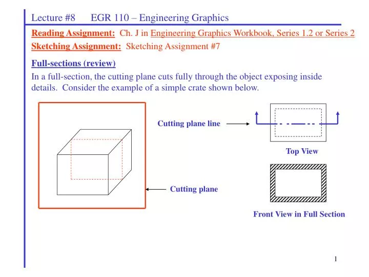
Cutting plane line Top View Cutting plane Front View in Full Section Lecture #8 EGR 110 – Engineering Graphics Reading Assignment:Ch. J in Engineering Graphics Workbook, Series 1.2 or Series 2 Sketching Assignment:Sketching Assignment #7 Full-sections (review) In a full-section, the cutting plane cuts fully through the object exposing inside details. Consider the example of a simple crate shown below.
Cutting plane line Top View Cutting plane Front View in Half Section Lecture #8 EGR 110 – Engineering Graphics Half-sections Half sections are often used for symmetrical objects. If the inside details are exposed on one half of the object, then the other half should be identical, so outside details are shown instead. With a half-section, a cutting plane cuts halfway through the object, exposing inside details on that half, as illustrated below. Consider the example of a simple crate shown below.
Lecture #8 EGR 110 – Engineering Graphics • Notes on half -sections: • Half-sections are used for symmetrical objects. • The cutting plane line should only have one arrow. • The sectioned half and the un-sectioned half should be separated by a center line. • Hidden lines are generally shown in the un-sectioned half of the drawing. Illustration from the textbook: Engineering Graphics Workbook, Series 1, p. J-5 The cutting plane cuts half way through the object. The cut out portion is discarded. Standard 3-view layout with the front view shown in half-section. Note that the cutting-plane line is shown in the top view.
Top View Top View Front View Front View in Half Section Lecture #8 EGR 110 – Engineering Graphics Example: Replace the front view in the drawing below with a half-section. Also show the cutting-plane line.
Lecture #8 EGR 110 – Engineering Graphics Revolved Sections (Conventional Revolutions) Holes or other features in an object that are along a bolt circle are typically shown as if they have been rotated into the extreme position. The cutting-plane line is also drawn in a special manner to remind the viewer that the revolution of a feature has taken place. Example: The object shown below is the front view of a simple plate with three holes along a bolt circle and a center hole. Draw the right view in full-section using a conventional revolution. Show the cutting plane line.
Lecture #8 EGR 110 – Engineering Graphics Example: Draw the right view in full-section of the simple plate below using a conventional revolution. Show the cutting plane line.
Lecture #8 EGR 110 – Engineering Graphics Offset Sections Sometimes the natural place to put a cutting plane will miss cutting through certain key features. The features can be offset to make it appear as if the cutting plane cuts through them as well. The cutting-plane line should show this offsetting operation. Example: Reference: Engineering Graphics Workbook, Series 1, p. J-6
Lecture #8 EGR 110 – Engineering Graphics Example: The object below is a plate of uniform thickness with four holes. Show a right-side view with an offset section. Show the cutting-plane line.
Lecture #8 EGR 110 – Engineering Graphics Broken-out Sections Broken-out sections are used when only an irregular portion of the object is to be cut away to expose interior shapes. The cut is shown using a thick, irregular break line. Some examples might include using broken-out sections to show inside details of a pump housing, a gearbox, or an engine. Note that cutting-plane lines are not used with broken-out sections. Example: Replace the right-view shown below with a right view with broken-out section. Use a break line in the right view.
Rod Rod Pipe Pipe Lecture #8 EGR 110 – Engineering Graphics Conventional Breaks (in solid rods and pipes) Breaks in rods and pipes are often given a 3-dimensional appearance using section lines. A conventional break (denoted B) is shown in the figure below from the text. Reference: Engineering Graphics Workbook, Series 1, p. J-9 Example: Add conventional breaks to the rod and pipe shown below.
Lecture #8 EGR 110 – Engineering Graphics Simplified Threads Simplified threads are typically shown on drawings (rather that full details of thread size, pitch, etc.) Several examples are shown in the figure below from the text. Reference: Engineering Graphics Workbook, Series 1, p. J-9
Lecture #8 EGR 110 – Engineering Graphics Revolved Sections Revolved sections are used to show cross-sectional areas on elongated parts in order to clearly show the shape of the parts. The revolved sections is essentially a thin slice of the part which is rotated into the plane of the view. This sectioned view is superimposed on the regular view. Two examples are shown below from the text. Example 2 Example 1 Reference: Engineering Graphics Workbook, Series 1, p. J-9