Download
1 / 28
360 likes | 706 Views
STS 201 3/14 Exercise 4 Ľ. Maceková. Link Budget. Energetick á bilancia satelitnej linky. Satel l it e. MOD. Acoustic d a ta. U/C. HPA. DIP. DEM. D/C. LNA. LNA. Fre quency convertor. HPA. G /T EIRP. DIP. DIP. HPA. LNA. Transpond e r. Ant e n na.

E N D
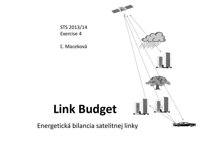
STS 2013/14 Exercise 4 Ľ. Maceková Link Budget Energetická bilancia satelitnej linky
Satellite MOD Acoustic data U/C HPA DIP DEM D/C LNA LNA Frequency convertor HPA G/T EIRP DIP DIP HPA LNA Transponder Antenna Attenuation by precipitation Attenuation by precipitation Blocking Shielding ! Antenna Multipath propagation and fading (because of reflections) Antenna, G/T, EIRP, C/No Propagation path Terrestrial exchange Mobileterrestrial station Propagation path Satellite Fig. Illustration of several satellite link aspects [2]
Problems: • noise • gains and losses (also gains of antennas) • blocking • attenuation by surrounding environment (shielding by vegetation, rain - in the case ofKa-band and mm-waves) • multipath broadcasting (multiple reflections) – multipathfading • reflection from sea level in the case of maritime communications But, at first, we must familiarize with: decibel measure of power, gain, attenuation,etc. noise power, SNR, noise temperature
Antenna gain– in dependence on generalized aperture and referenced to gain of isotropic radiator: Gain ofparabolicantennain dependence on both dish diameter an efficiency: ηA ... effective radiated surface of antenna – depends on diraction of setting of antenna =Aef[m2] A ... aperture (physical surface, passed by e-m radiation) [m2] η ... efficiency ofaperture(0,35-0,75) [-] λ ... wavelength[m] ... in comparison with isotropic antenna GdBi= 10 log G [dBi] D ... diameter of dish (or of reflector, or of array of radiating elements, i.e. of aperture) [m] Example: η=55%, f=11GHz, D=1m. G=? Results: about 7299 and 38dBi - actual gain isalways< than value declared by producer (connection, direction and other unfavourable conditions) Example: Calculate λ of frequency channel at 900 MHz.
Decibels device or signal path P1 P2 G (L) If P2> P1 Gain Definition of dBmanddBW - if we transform: [W alebo mW] P[dBm]=10logP[mW] P[dBW]=10logP[W] …… > 0 dB and by definition of dBm: Then– similarly: attenuation, diminution, Loss = 10log(P2 /1mW) – 10 log( P1 /1mW) G[dB] = P 2[dBm] – P 1[dBm] 5 P1 > P2; L > 0 dB
Examples... 1 W ? dBW 1mW ? dBW 1mW ? dBm 10 mW ? dBm 35 mW ? dBm P1 = 1mW, P2 = 10 W, A = ? (A… Attenuation) P = 35 dBm ? mW P = - 15 dBW ? W
Noise (Šum)
Noise, Signal-to-NoiseRatio SNR (S/N in [-]) and Signal-to-NoiseRatio in [dB] , Noise Figure F (or NF), noise voltage, noise power, Power Spectral Density of noise (PSDN), ... Effective noise voltage (byNyquist [2]) k – Boltzmannkonstant= 1,38. 10-23Ws-1K-1 T – absolut. temperature[K] R – equiv. resistivity[Ω] B – frequency bandwidth [Hz] (thermalnoise/whitenoise/Gaussadditivenoise) Signal-to-Noise Ratio in non-units [-] and in [dB] S/N ... ratio [W,W; result is without units] SNRdB = 10 log (S/N) [dB] = SdBm– NdBm[dB] (S/N)in, (S/N)out, SNRin, SNRout S ... signal power N ... noise power (šum=noise) SNR ... signal-to-noiseratio
Power of noise (if matched connecting: Rsource=RLoad =R) density of energy N0 – power spectral density of noise (power over unit of freq. spectrum, i.e. over1 Hz): [W/Hz] ...symbolicnotation for dB-calculi if in [dB], so as follows: [dBW/Hz] [dBW/Hz] Example: Evaluate density of noise energy of resistor at temperature 27°C Result: -203,8 dBW/Hz
Noise is property of every substanceeachel. amplifier, beyond amplifying of entering signal and noise, adds its own noise, as well. important parameter of active el. equipments (antennas, amplifiers, : Noise Figure(F) of device with gainG Sin,Nin, SNRin Sout,Nout, SNRout G...Gain F Sout = G . Sin Nout=G.Nin+Nown NoisefigureNF, alebo len F – šumové číslo aktívneho zariadenia (zosilňovača, antény atď.) We know: S/N ... ratio [-] SNRdB = 10 log (S/N) [dB] (S/N)in, (S/N)out, SNRin, SNRout [without units] where: Te...equivalentnoise temperature of el. deviceat the input T0 ...operational(circumstances) physical temperature And then in dB: F = 10 log F = SNRin[dB]– SNRout[dB] [dB]
Example 1: Evaluate the noise figure of amplifier at circumstances temperature T0 = 300 K and at Tin = 400 K. Result: 3,7 dB Example 2: Calculate the equivalent input noise temperature of amplifier, if we know the circumstances temperature To = 290 K, and noise figure NF=4 dB. Result: Te = 438,8 K
Noise Figure(FL) of devicewith insert loss L (attenuation)– feed lines, cables, connectors, etc. Sin,Nin, SNRin Sout,Nout, SNRout L ...Loss FL L > 1 Sout= Sin/L; Sout<Sin inputnoise outputnoise noise figure FL – šumové číslo zariadenia: Then input noise temperature: Andoutput noise temperature.: [without units] Te ...equivalent noise temperature at the input T0 ...operational (circumstances) temperature Tout ... Output noise temperature Then in dB: FL[dB] = 10 log FL[dB]
Example - both input and output noise temperatures of loss device: Circuit has loss 2,5 dB, operational temperature is400 K. Evaluate equivalent noise temperature at both his input and output ports. Results: Te = 311,3 K, Tout=175,1 K Outcome: Circuit with loss decrements equivalent noise temperature – suppresses noise!
Ga, Ta P1 G1 L1 L2 G2 Overall equivalent noise temperature of the complete cascade (converted into the point P1; not yet with antenna): It depends almost on noise properties of first stages (for examples antenna feed L1 and input amplifier G1) !!(all G are >> 1) That is, why requirement of LNA– LowNoiseAmplifier – of receiver is important and crucial (our aim is: as best / as high SNR as possible!!). orLNC– Low Noise Convertor
... with considering of antenna: Total noise temperature of system Tsat the input of receiver with antenna: (*) or : T=Ta.a + (1-a)T0+(F-1)T0 where: TR... noise temperature of the first amplifier stage of receiver (Low Noise Amplifier - LNA); TR= (F-1).T0 Lf ... loss of feed line (between antenna andLNA); LF=1/a ... about 1/0,95 Ta... noise temperature at output of antenna (about80 K to100K in L-band)
The next parameters of system: G/T - Figureofmerit(Effectivity of system, Systémový zisk) • the ratio of the gain and noise temperature of equipment - important parameter – higher the better • G/T of antennas mostly contains also noise temperature of convertor Example: Evaluate figure of merit of antenna withLNC-convertor.Noise figure ofLNCisF=1,3, gain of antennaatmeanfrequency12,1GHz is34,75 dBi, its noise temperature is31,68K, loss between radiator and convertoris about a=0,95, loss because of inaccurate bearing and polarization setting is about b=0,9. Consider reference operational temperature T0=290K. Solution: We use equation (*) for equivalent noise temperature of system of antenna with convertor: T=Ta.a + (1-a)T0+(F-1)T0; and for operational gain of antenna Gp=a.b.G[-]. then Gp/T=… Result: 17,7 K-1... 12,48 dB/K
Power flux density- PSD,EffectiveIsotropicRadiatedPower-EIRP
Power flux density = power over surface ... Φ = P/ A [W/m2] Φi = Pt / 4πR2 ... Φi ... density of radiated power of isotropic antenna(or PFD- PowerFluxDensity) [W/m2] Pt...radiated power[W] R .... distance between transmitting and receiving antennas [m] thereafter: • = its radiation effectivity in comparison with reference isotropic antenna (that means: the gain is the result of the ratio of 2 power densities!): Gain of directional antennaGa Ga = Φa/ Φi Ga [dBi]= 10 log(Φa/Φi) ... [dBi] ... note.: G of isotrop. antennais1 (i.e.0 dBi) Note: PFD on the Earth surface (of the signal from satellite transmitter) – fallswith horizontal distance from nadir(nadir or boresight – zamierenie - the point “under” the satellite; it relates with directional characteristic of antenna...)
EIRP ... Equivalent (Effective) Isotropic Radiated Power of satellite transmitter EIRP= Pt .Gt [-] [W; W, -]EIRP= Pt . Gt = Pt . (Φt/Φi) = ... = Φt. 4πR2 or, in dB: EIRP[dBW] = 10 log Pt[W] + Gt[dBi] Pt … radiated power (of transmitter) [W] Gt ... gain of transmitting antenna (on thesat.) Example: IfEIRPof transmitter inGEOsystem is48 dBW, calculate the maximal PFD on the Earth. result: -114 dBW/m2
next parameters of system: Quality of receiving signal - Signal-to-Noise Ratio in Satellite Communication C/N – signal to noise ratio, or quality of receiving signals (C-Carrier-nosná,t.j. nosná frekvencia signálu, N-Noise-šum) - it is ratio of signal and noise at the input port of Earth station receiver (before, we designate it as power to noise ratio SNR). seenext (C/Ν)[-]= Pt [W] .Gt.Gr..b / (k.T.B) Pt...transmitter power, Gt,Gr...gains of either transmitting or receiving antenna, b- free space loss between antennas in dB: C/Ν[dB]= Pt [dBW]+Gt[dΒ]+Gr[dB]+b[dB]-10logk-10logT-10logB When noise power density N0 in C/N is considered, we can write:
b...útlm voľného priestoru od vysielacej antény ku prijímacej: λ...vln.dĺžka R...vzdialenosť (napr. 36.106 m pre GEO) Príklad: Vypočítať útlm pre systém GEO pri frekvencii 11 GHz. Výsledok: -206dB
Now, link energy budget: všetky faktory sa započítajú ako prírastky (+) alebo mínusy (-) v [dB] (viď obr. na 2. slide) Tx EIRP • Transmission: • +power of HPA • transmission loss • (cables and connectors) • + Gain of antenna • loss of bearing of Tx antenna- Loss in the free space • Athmosphericloss (gases, clouds, precipitations) • - loss of bearing of Txantenna • Receiving • + gain of antenna • Receiving losses • (cables and connectors) • + noise temperature Rx Pr source [1]
Signal-to-Noise Ratio (C/N0) in total satellitelink (up anddowntogether)
In communications up- anddown– the total Signal-to-Noise Ratio T ...total U ...uplink D ...downlink I0 ...intereference noise (***) Quality of receiving depends on the worste quality in some partial section of link (the principle of the “weakest article of the chain”)
[1] Example of calculation: Communication from Earth station to aeroplane station through satellite in the system ETS-V. (the older experimentalsystem for communicationground-aircraft via satellite) Notes: GES ... gate Earthstation, AES ... aircraftEarthstation. FromGEStosatellite(uplink): GESEIRP.....................................................60,7 dBW propagation loss.........................................199,4 dB (d = 37270 km, f = 6GHz) satellite antenna gain..................................21,7 dBi feeder loss............................................3,0 dB uplink total C = 60,7-199,4+21,7-3,0= -120,0 dBW N0 =10log(kTB)= -228,6+10log300+10log1Hz=-203,8 dBHz (nie je zmienka o š.pásma, takže uvažujeme kvalitu na 1 Hz) s (C/N0)U= -120 + 203,8 = 83, 8 dBHz • Zo satelitu na lietadlo (downlink): • sat. EIRP .........................................30,5 dBW • propagation loss...... 188,5 dB (d = 41097 km, f = 1,5 GHz) • AESantenna gain................................14,0dBi • antenna tracking error..............0,5dB • feeder loss...............................3,0 dB • downlink total C = 30,5-188,5+14,0-0,5-3,0= -147,5 dBW • N0 =10log(kTB)= -228,5+10log300=-203,8 dBHz • (C/N0)D= -147,5 + 203,8 = 56,3 dBHz continue
Calculation by (***) : The result confirms, that total quality of communication channel equals tothe worst one from partial links.
Zdroje: [1] J. Montana:Introduction to Satellite Communications, GeorgeMason Univ. 2003 [2] Mobilné satelitné komunikácie [3] S.Ohmori, H. Wakana, S.Kawase: Mobile satellite communications, Artech House, 1998.