Download
1 / 24
240 likes | 479 Views
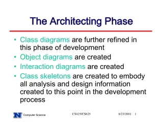
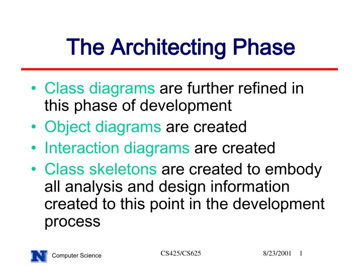
The Architecting Phase. Class diagrams are further refined in this phase of development Object diagrams are created Interaction diagrams are created Class skeletons are created to embody all analysis and design information created to this point in the development process. Class Skeletons .

E N D
The Architecting Phase • Class diagrams are further refined in this phase of development • Object diagrams are created • Interaction diagrams are created • Class skeletons are created to embody all analysis and design information created to this point in the development process CS425/CS625
Class Skeletons • We will preview class skeletons to better understand the objectives of design • Class skeletons are partial class definitions • Class skeletons should be heavily commented, so that the purpose of all attributes, methods, and constructors is clear • Class skeletons are the basis for the implementation phase of development CS425/CS625
Contents of Class Skeletons • A list of the roles the class plays within the system • Information concerning when objects of the class are created and deleted (information maintenance) • For each role, the semantics of the class • All attributes with access modifiers, types, names, and semantics • For all constructors and methods, their signature, semantics, preconditions and postconditions CS425/CS625
LMS Class Skeleton CS425/CS625
System Decomposition • Adds detail to the previous system representation • Can be done iteratively or in a traditional, waterfall manner • Each phase in the system development decomposes the system further • Leads to a blueprint for implementation CS425/CS625
More UML • Access Modifiers • + means public • - means private • # means protected • Constraints (restriction on the class) { } • E.g {Students may check out at most 25 items} • Tagged values also use { } • E.g. {Requirement #5} CS425/CS625
More UML: Multiplicity • Multiplicity or cardinality is represented above by the 0..1 and 0..* • The above diagram indicates that a resource is checked out by 0 or 1 patrons and that each patron may check out 0 to many resources 0..1 checks out 0..* Patron Resource Borrower CS425/CS625
More UML: Aggregation • The solid diamond indicates that the Overdue form letter class consists of Patron and Resource objects. Solid diamond indicates that Patron and Resource classes exist in their own right Patron Overdueform letter Resource CS425/CS625
Aggregation • Example from LMS where classes do not exist independent from aggregating class? CS425/CS625
Interaction Diagrams • Interaction diagrams model dynamic aspects of the system by specifying the interaction among objects to produce a particular behavior • Two types of interaction diagrams are defined in UML • Collaboration diagrams, which emphasize the structural organization of objects that send and receive messages • Sequence diagrams, which emphasize the time ordering of the messages passed between objects CS425/CS625
Notational Elements of Interaction Diagrams • The object name is optional in the depiction of an object in UML notation • An object is distinguished from a class in UML notation by the colon and underlining of the class name Object Link Message method(parameters) Object: class CS425/CS625
LMS: Collaboration Diagram : Library System validatePatron(MemDate) getResource(ResourceID) Checkout(ResourceID) getPatron(PatronID) update(Patron) : Patron : LibraryDatabase create(LibraryDatabase) CS425/CS625
Steps for Creating Collaboration Diagrams • Identify a behavior to model • Identify participating class and their relevant interrelationships • Identify a specific scenario to model • determine necessary message passing to carry out the behavior • Introduce solution for object persistence, if needed CS425/CS625
Sequence Diagrams • Like collaboration diagrams, sequence diagrams model dynamic aspects of the system by specifying the interaction among objects to produce a particular behavior • Sequence diagrams specify the time ordering of messages • Sequence diagrams show the life span of each object CS425/CS625
Check out resource Sequence Diagram : Library System : Patron : LibraryDatabase getResource(ResourceID) getPatron(PatronID) create(LibraryDatabase) validatePatron(MemDate) CS425/CS625
Evaluating Design • Modeling software helps us produce correct, well- structured systems • The resultant models can also be scrutinized for potential data integrity problems • For example, in the LMS system, having update methods execute separately for the Patron and Resource objects may result in data integrity errors if system failure occurs between the initiation of the first method and the termination of the second method CS425/CS625
Object Diagrams • Models a set of objects and their interrelationships during a system snapshot • A system snapshot is the state of the software system at a selected moment of time • Object diagrams model another static perspective of the system • Unlike other diagrams, object diagrams may contain multiple instances of the same class CS425/CS625
LMS Case Study: Object Diagram (partial) :Book currentP: Student : List name = “SOTY”author=“b. hooks”ISBN= ... name=“Gert Stein”libraryID=6747632homephone=5554321workphone=5551234membership=05011999expire=05012002 :Book name = “FOF”author=“Ehrenreich”ISBN= ... CS425/CS625
Steps for Creating Object Diagrams • Identify a system snapshot within a scenario to model • Identify participating classes and their interrelationships • Identify all allocated objects at the time of the snapshot • Show the state of each object in the snapshot • Determine all interobject links CS425/CS625
Code Reuse • Collaboration diagrams are of particular use in patternscavenging • Pattern scavenging involves studying the various diagrams produced during analysis and class design to identify patterns of class interaction • Once such patterns are found, they should be evaluated to determine if they can be effectively reused CS425/CS625
Reuse in LMS Resource CheckableResource ReserveResource Book Electronic Media CS425/CS625
Guidelines for Class Design • Always keep data private • Always initialize data in a constructor • Do not use too many related primitives • Not all attributes need individual accessor or mutator methods • Order elements comprising class definitions consistently • Break up overly complex classes into multiple classes • Name classes, methods and attributes well CS425/CS625
Verification of the Class Design • All system requirements developed during analysis must be addressed during design • All design documents must cross reference requirements from the requirements specification • All required attributes and methods must be used properly • Eg data integrity of attributes must be enforced by update methods • The modules comprising the system must work together properly CS425/CS625
Next • Distributed systems • Corba, Java-RMI • Design Documents – Reviews • Implementation – Reviews • Testing • Integration • Project Presentations CS425/CS625