Download
1 / 28
290 likes | 514 Views
Software Requirements. Part I: Introduction. Business Analysis Modeling Techniques. The International Institute of Business Analysis specifies over 50 Business Analysis Techniques. The most important modeling techniques are: Data Flow Diagrams Data Modeling (ERD and Class Diagram)

E N D
Software Requirements Part I: Introduction
Business Analysis Modeling Techniques The International Institute of Business Analysis specifies over 50 Business Analysis Techniques. The most important modelingtechniques are: • Data Flow Diagrams • Data Modeling (ERD and Class Diagram) • Organizational Modeling • Process Modeling (Flowchart, Activity Diagram) • Scenarios and Use Cases • Sequence Diagrams Source: BABOK Guide V3
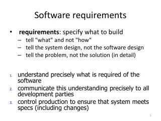
Logical vs. Physical Models • One of the ways to document and elicit requirements is with the development of different models • Requirements models are logical models • Models that show what the system is required to do without committing to any one technology • Design models are physical models • Models that show how the system will actually be implemented
Today’s Agenda • Introduction • Module I: Use Case Diagrams • Activity: Use Case Diagrams • Review and Closedown
Software Requirements Part II: Use Case Diagrams
The Use Case Diagram • A use case diagram is a graphical model that summarizes the functions (functionality) that must be supported by the new system. • Think of a use case diagram as the functional description of the entire system. • To perform use case analysis, we look at the system as a whole and try to identify all of its major uses.
Use Case Diagram Notation • “A use case is a coherent unit of functionality provided by a system, a subsystem, or a class as manifested by sequences of messages exchanged among the system and one or more outside interactors (called actors) together with actions performed by the system.” UML Specification • In other words, a Use Case describes an activity the system carries out in response to an event. • A use case is shown as an ellipse containing the name of the use case.
Actors • “An actor defines a coherent set of roles that users of an entity can play when interacting with the entity. An actor has one role for each use case it communicates with.” UML Specification • An actor may be shown as a class rectangle with the stereotype «actor». The standard stereotype icon for an actor is the “stick man” figure with the name of the actor below the • figure.
Automation Boundary and Organization • A boundary line can be drawn around the complete set of use cases. This boundary is the automation boundary. • It denotes the boundary between the environment, where the actors reside, and the internal components of the computer system.
Use Case Relationships There are standard relationships among use cases or between actors and use cases: • Association is the participation of an actor in a use case. This is the only relationship between actors and use cases. • Extend is the relationship between two use cases and indicates that the instance of the use case may be extended by the behavior of the other use case. The base use case may stand alone. • Generalization indicates that one use case is a specialization of another use case. • Include indicates that the instance of a use case will also include the behavior of the other use case. The included use case never stands alone. It only occurs as a part of some larger base that includes it.
Actor Relationships • Generalization – A generalization from an actor A to an actor B indicates that an instance of A can communicate with the same kinds of use-case instances as an instance of B. • An generalization between actors is shown by a generalization arrow, i.e. a solid line with a closed, hollow arrow head. The arrow head points at the more general actor.
Elementary Business Processes (EBPs) • The appropriate level of detail for identifying use cases is one that focuses on elementary business processes (EBPs). • An EBP is a task performed by one person in one place in response to a business event that adds measurable business value and leaves the system and its data in a consistent state. • Note that each EBP (and so each use case) occurs in response to a business event. These events drive or trigger the system’s processing, and they provide the basis for decomposing the system into separate activities or use cases.
Use Case Development Techniques There are several techniques recommended for identifying use cases: • One technique is called the user goal technique, which is to identify users (actors) and list the goals each type of user has when using the system. These user goals are named using a verb-noun syntax. • Another comprehensive technique is called the Event Decomposition technique. • A third technique is called the CRUD technique, where CRUD stands for Create, Read or Report, Update, and Delete. With this technique, the analyst analyzes each persistent object in the system to ensure that use cases have been defined to perform all of the CRUD processes on those objects.
Event Tables An event table is used to list events in rows with key pieces of information about each event in columns. The columns include the: • Trigger: A signal that tells the system that the event has occurred, either the arrival of data needing processing for an external event or a point in time for a temporal event. • Source: An external agent or actor that supplies data to the system for an external event. • Activity: Behavior that the system performs when an event occurs (similar to a use case). • Use case: A series of actions that a system performs that results in a defined outcome (similar to an activity). • Response: An output produced by the system that goes to a destination. • Destination: An external agent or actor that receives data from the system.
Event Table Example • Source: John W. Satzinger, et al. Systems Analysis and Design in a Changing World, Fifth Edition, 2009, Boston MA: Thomson Course Technology.
CRUD Analysis for Identifying/Confirming Use Cases • CRUD – create, read/report, update, delete • Information Engineering (IE) technique to identify event table or directly develop use case diagram • Compares identified use cases with domain model class diagram • Every class in class diagram must have use cases to support creating, reading, reporting, updating, and deleting object instances • Confirms system integration requirements
Types of Events • External • Outside system • Initiated by external agent or actor • Examples • Management wants some information • Customer requests a tracking number • Temporal • Occur as result of reaching a point in time • Based on system deadlines • Example: Monthly payroll • State • Something inside system triggers processing need • Example: Calculation of shopping cart totals, e-mail an invoice etc.
System Controls • Some events are related to specific technologies or system controls. System controls are checks or safety procedures put in place to protect the integrity of the system. • These are important in the design phase but not during analysis. • For example, a user logs into the system, the user changes his or her password. • System controls are not events that define the functional requirements for the system. Rather, they involve the need to design system controls to protect the system. • The perfect technology assumption is a concept to help the analyst determine if an event is required in the analysis phase. • Under perfect conditions, equipment never breaks down, the capacity for processing and storage is unlimited, and people operating the system are completely honest and never make mistakes.
Use Case Diagram Example http://www.cdc.gov/cancer/npcr/informatics/aerro2/hospitals/h_business_use_case_diagram.htm
Suggested Reading • OMG Unified Modeling Language (OMG UML) Version 2.5 http://www.omg.org/spec/UML/2.5/
Use Case Descriptions • Use case descriptions provide details of each Use Case including preconditions, post-conditions, sequence of activities, and exception conditions • Describes each actor interacting with computer system step-by-step to carry out business activity • May have several scenarios for a use case, each a specific use case instance • Several levels of detail • Many analysts prefer to write narrative descriptions of use cases instead of drawing activity diagrams
How to Develop a Use Case Diagram • Draw your system boundary and title your Use Case Diagram • Identify and draw actors • Identify system functionality at the EBP level: • If you have a description of the desired functionality, highlight all verbs • Users’ goals/needs to be accomplished via the system • Think of business events demanding system’s response • Draw eclipses for each identified system functionality and name your Use Cases (verb + noun) • Connect actors with use cases • Perform CRUD Analysis • Specify include and extend relationships between use cases • Review for completeness
Team Activity – Use Case Diagrams (15 minutes) • Next slide provides a description for Hornet Burgers. • Examine the description and then develop a Use Case Diagram based on the description provided (make the necessary assumptions and model the proposed system).
Use Case Diagram Team Activity • Hornet Burger's customers work in the downtown area, so Bob and Thelma think a noon delivery service will offer an additional convenience to their customers. • Bob envisions the delivery system operating as follows. When a customer calls and places a delivery order, a Hornet Burger employee records the order on a multiform order ticket. The employee captures such details as customer name, business or home address, phone number, order placement time, items ordered, and amount of sale. The multiform document is sent to the kitchen where it is separated when the order is ready for delivery. • Two copies accompany the order; a third copy is placed in a reconciliation box. When the order is prepared, the delivery person delivers the order to the customer, removes one order ticket from the food bag, collects payment for the order, and returns to Hornet Burger. Upon arriving at Hornet Burger, the delivery person gives the order ticket and the payment to Bob. Each evening, Bob reconciles the order tickets stored in the reconciliation box with the delivery payments and matching order tickets returned by the delivery person. At the close of business each evening, Bob uses the data from the order tickets to update the goods sold and inventory files.
Review Today’s Agenda • Introduction • Module I: Use Case Diagrams • Activity: Use Case Diagrams • Review and Closedown Any Questions?