Download
1 / 27
290 likes | 667 Views
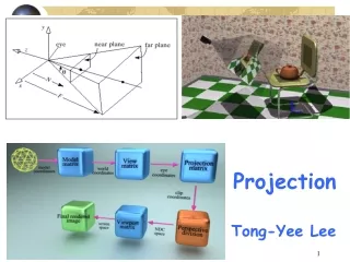
Projection. Pradondet Nilagupta Dept. of Computer Engineering Kasetsart University. viewport. NDC’s. World. Transformation Projection pipeline. This is really called a projection transform. Normalize Coordinate Device. Definition (1/2).

E N D
Projection Pradondet Nilagupta Dept. of Computer Engineering Kasetsart University 204481 Foundation of Computer Graphics
viewport NDC’s World Transformation Projection pipeline This is really called a projection transform Normalize Coordinate Device 204481 Foundation of Computer Graphics
Definition (1/2) • Transform points in a coordinate system of dimension n into points in a coordinate system of dimension less than n • The projection is defined by projectors: lines that start from the centre of projection, pass through points on the 3D object and then fall onto the projection plane 204481 Foundation of Computer Graphics
Definition (2/2) • Center of projection (CoP): the position of the eye or camera with respect to which the projection is performed (also eyepoint, camera point, projection reference point) • Projection plane: in a 3D->2D projection, the plane to which the projection is performed (also viewplane) 204481 Foundation of Computer Graphics
Planar Projections Perspective: Distance to CoP is finite Parallel: Distance to CoP is infinite 204481 Foundation of Computer Graphics
Planar Geometry Projection Parallel Perspective Orthographic Oblique One-point Two-point Top (plan) Cabinet Three-point Front elevation Cavalier Other Side elevation Isometric Other Projections 204481 Foundation of Computer Graphics
Parallel Projections (1/2) • Orthographic: Direction of projection is orthogonal to the projection plane • There are several types of `axonometric' or parallel projections commonly in use (not orthographic). • Trimetric. Here the coordinate axes remain orthogonal when projected. • Dimetric. Two of the three axes are equally foreshortened when projected. • Isometric. All three axes are equally foreshortened when projected. 204481 Foundation of Computer Graphics
Parallel Projections (2/2) • Oblique: Direction of projection is not orthogonal to the projection plane; projection plane is normal to a principal axis • Cavalier: 45° angle with the projection plane • Cabinet: 63.4° angle with the projection plane • All components of the object appear in the 2D image exactly the same size as they do on the original 3D object. • Useful for CAD, but not for visual realism 204481 Foundation of Computer Graphics
A Section AA Engineering Drawing 204481 Foundation of Computer Graphics
side elevation view Front elevation view Simple viewing: parallel projection • Orthographic • preserves all dimensions • Oblique • preserves some dimensions 204481 Foundation of Computer Graphics
z O y x Example of Orthographic Projection on to plane z=0 204481 Foundation of Computer Graphics
Isometric Projection (1/2) • There are three stages in this projection. • Rotate through angle A about y axis. • Rotate through angle B about x axis. • Project onto plane z=0. cosA 0 sinA 0 sinBsinA cosB -sinBcosA 0 0 0 0 0 0 0 0 1 204481 Foundation of Computer Graphics
Isometric Projection (2/2) Matrix of Isometric Projection 0.7071 0.0 0.7071 0.0 0.4082 0.8166 -0.4082 0.0 0.0 0.0 0.0 0.0 0.0 0.0 0.0 1.0 204481 Foundation of Computer Graphics
Example: Isometric View 204481 Foundation of Computer Graphics
OpenGL Parallel View glOrtho(left, right, bottom, top, near, far); 204481 Foundation of Computer Graphics
z O y x E Perspective Projections Projection on to z=0 • Perspective projections are often considered “more realistic”. • The size of the projected object depends on its distance from the viewpoint. • Lines are projected from viewpoint E through vertex and onto plane. 204481 Foundation of Computer Graphics
horizon horizon Perspective Projections • One-point: • One principal axis cut by projection plane • One axis vanishing point • Two-point: • Two principal axes cut by projection plane • Two axis vanishing points • Three-point: • Three principal axes cut by projection plane • Three axis vanishing points 204481 Foundation of Computer Graphics
(x, y, z) +Z +Z (xproj, yproj, 0) -Z (0, 0, -d) -Z One point Projection • Center of Projection at the origin with viewplane parallel to the x-y plane a distance d from the origin. • Center of Projection on the negative z-axis with viewplane in the x-y plane. 204481 Foundation of Computer Graphics
Matrix for one-Point Projection Center of Projection on the negative z-axis with viewplane in the x-y plane. Center of Projection at the origin with viewplane 204481 Foundation of Computer Graphics
Example of Perspective Projection Viewing frustum looks like a truncated Egyptian pyramid 204481 Foundation of Computer Graphics
Defining Perspective Projections • glFrustum( l, r, b, t, n, f ); • frustum not necessarily aligned down line of sight • good for simulating peripheral vision • gluPerspective(fovy,aspect,n,f ); • frustum centered down line of sight • more general form • reasonable values: • aspect should match aspect ratio of viewport 204481 Foundation of Computer Graphics
Projections in OpenGL Objects not in the view volume are clipped 204481 Foundation of Computer Graphics
Perspective Projection • Nonuniform foreshortening – images of objects farther from the center of projection are reduced in size • We apply a 4 x 4 projection matrix after the model-view matrix 204481 Foundation of Computer Graphics
OpenGL for Perspective Projection • glFrustum( l, r, b, t, n, f ); • gluPerspective( fovy, aspect, n, f ); • then use glFrustum() 204481 Foundation of Computer Graphics
OpenGL Perspective (1/2) glMatrixMode(GL_PROJECTION); glLoadIdentity( ); glFrustum(left, right, bottom, top, near, far); 204481 Foundation of Computer Graphics
OpenGL Perspective (2/2) gluPerspective(fovy, aspect, near, far); fov is the angle between the top and bottom planes 204481 Foundation of Computer Graphics
Standard Viewing Volume 204481 Foundation of Computer Graphics