Download
1 / 21
210 likes | 300 Views
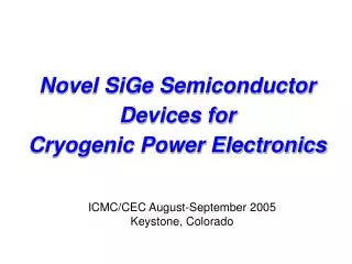
Novel Semiconductor Phase Shifters. EE Department. KFUPM. Sheikh Sharif Iqbal, PhD Mahmoud Dawoud, PhD. IEEE-TEM 2000. 1. LOW LOSS, ACCURATE phase shift 2. Introduction: The gyromagnetic properties of magnetized ferrite is widely used for phase shift section.

E N D
Novel Semiconductor Phase Shifters EE Department. KFUPM Sheikh Sharif Iqbal, PhD Mahmoud Dawoud, PhD IEEE-TEM 2000
1. LOW LOSS, ACCURATE phase shift 2. • Introduction: • The gyromagnetic properties of magnetized ferrite is widely used for phase shift section. • Due to its frequency limitations and high cost, gyroelectric properties of magnetized semiconductors are exploted here for designing millimeter wave phase shifters.
1Damping LOSS 2 CW and CCW 3 -CP; until damping losses stop • Review of magnetized ferrite phase shifters: • When magnetized, the magnetic moments of spinning electrons starts to rotate around the axis of Ho, until unidirectional alignment. • Direction & frequency of rotation depends on Ho. Assume the direction is same as -CP wave • Propagating EM wave interacts and causes aligned magnetic moments to restart rotating.
1. 2. M. field is Ho 3. See fig • Circularly polarized modes are fundamental for EM wave propagation in biased ferrites. • So, interaction between ferrite magnetic moments (in -CP direction) and magnetic field component of EM wave ( to Ho) results : =›Accelerated -CP component of mag. field. =›Retarded +CP component of magnetic field. • So, two CP’s are rotated by different angles. Consequently, incident LP wave is rotated.
1.rotation of LP 2. Until saturation. 45+45=90 • Increasing Ho or thickness of the phase phase shift section, increases the phase-shift • The direction of phase shift depends on the direction of Ho and not in the direction of propagating EM wave => nonreciprocity.
In ferrites, the anisotropic interaction of the magnetic moments and the EM wave is governed by its permeability tensor; • Typically, [r]50-3000 and r10-20. • EM field components within ferrite are expressed by substituting [r] and boundary condition into Maxwell’s equations.
C.E. of Ferrite filled circular wave-guide : where Ko2 = 2oo , ef f= (2-2)/ , R=radius and
eff={2Hin2-f2+22HinM+(M)2}/{2Hin2-f2+2HinM}eff={2Hin2-f2+22HinM+(M)2}/{2Hin2-f2+2HinM} YIG G 113
Magnetized semiconductor phase shifters: • The interaction of Electric field (EM wave) and free electrons of biased semiconductor produces gyroelectric cyclotron motion (of electrons), responsible for phase shift action • The direction and magnitude of phase shift depends on the direction and magnitude of biasing magnetic field, Ho (and thickness) • Semiconductor phase shifters : nonreciprocal
According to drude model, the gyroelectric properties of semiconductor is described by;
C.E. of semiconductor circular wave-guide : where Ko2 = 2oo , r= dielectric constant, radius R
-f plot of magnetised semiconductor at Ho=150 KA/m, r=16, N=1e18 m-3, m*/me=0.014, R=1mm InSb
Conclusion: • Phase shift per unit length is observed for a circular YIG G113 ferrite phaser of 5 mm in radius and magnetized by Ho= 0.5 mT • Phase shift per unit length is plotted for a magnetized InSb semiconductor phaser of 1mm radius and magnetized by Ho=0.19mT • For ferrites, the frequency range of 4.5 to 9 GHz was plotted and for semiconductor the frequency range of 28 to 32.5 GHz was observed. The phase shift is noted to increase with frequency.