Download
1 / 30
310 likes | 461 Views
Transparent Nodes. Subsystems, Architecture & Cost Scaling. Transparent Node Architecture. Overview. General Classification & Requirements 3D MEMS - Principle of operation Traditional Matrix-based Reconfigurable Optical Add & Drop Multiplexer (R-OADM) / Cross-Connect (OXC)

E N D
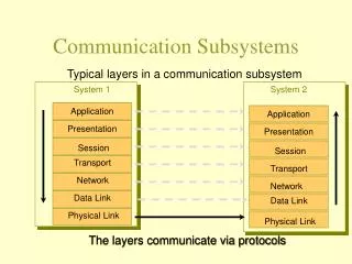
Transparent Node Architecture Overview • General Classification & Requirements • 3D MEMS - Principle of operation • Traditional Matrix-based Reconfigurable Optical Add & Drop Multiplexer (R-OADM) / Cross-Connect (OXC) • Wavelength or -Blocker • Functional Diagram • Node Architectures • Wavelength Selective Switch • Functional Diagram • Performance, Benefits & Open Issues • Node Architectures • Cost Scaling • References
Transparent Node Architecture Key requirements Performance • Low loss (most important on the through channels) • Support of ITU-T channel grid (100 GHz) with up to 40 wavelengths; 50 GHz grid and 80 wavelengths in the future • Ability of cascading through multiple nodes (say: 10 nodes) Flexibility • No service affecting modular upgrades • Fully flexible “any-to-any” connectivity remotely configured; no coloring restrictions, i.e. colorless ports • Option for sparse/selective wavelength conversion • Loop-backs may be required to enable link/OMS protection on OADMs Reliability • Low component count for high reliability • No single point of failure Operations integration • Management by, e.g. , a GMPLS control plane Cost • Low first-in cost according to “pay as you grow” • Built-in per-channel power equalization at least for the pass-thru (saves cost at other sites of the network) Requires interleaver at day one => loss/narrowing/cost
Transparent Node Architecture Overview • General Classification & Requirements • 3D MEMS - Principle of operation • Traditional Matrix-based Reconfigurable Optical Add & Drop Multiplexer (R-OADM) / Cross-Connect (OXC) • Wavelength or -Blocker • Functional Diagram • Node Architectures • Wavelength Selective Switch • Functional Diagram • Performance, Benefits & Open Issues • Node Architectures • Cost Scaling • References
Transparent Node Architecture Physical Principle: 3D Micro Electrical Mechanical System (MEMS) • 256x256 or larger non-blocking space switch in one switching stage can be achieved today. • Switching time: • down to 3 ms (NTT) • 10 ms (Calient) • Insertion loss: • down to 4 dB (NTT) • 1,5 dB (Calient) Source: Calient Networks Source: Lucent Technologies
Transparent Node Architecture Overview • General Classification & Requirements • 3D MEMS - Principle of operation • Traditional Matrix-based Reconfigurable Optical Add & Drop Multiplexer (R-OADM) / Cross-Connect (OXC) • Wavelength or -Blocker • Functional Diagram • Node Architectures • Wavelength Selective Switch • Functional Diagram • Performance, Benefits & Open Issues • Node Architectures • Cost Scaling • References
Transparent Node Architecture Traditional Matrix-based OADM • An OADM is assumed to be a device deployed within a “degree 2” node. • An (R)-OADM has a clear through path direction, especially when only a small fraction of channels is locally accessible. • Therefore, OADMs are typically used for traffic aggregation in regions within the today’s DT network. Monitoring Taps VOA MonolithicTransparent Switch Fabric (optional: Patch Cords) Demux Mux Local Drop / Add Between switch and Mux VOAs should be added, as here a power equalization is mandatory VOAs are not useful between Demux and switch (no power equalization needed at this place, taps might be placed here (again for monitoring) Usually an OA is placed in front of the Demux, optionally a tap can be placed between OA and Demux then for monitoring With your proposal one has no chance to compensate the switch fabric’s power inequalities.
Transparent Node Architecture R-OADM based on smaller per-switch fabrics • Moderately large space switches • Better modularity • Higher cabling effort Source: D9 of WP6
Transparent Node Architecture Assessment of Matrix-based Architectures Means 100% add/drop capability Advantages • No coloring restrictions: Any wavelength can be routed to any add-drop port. Disadvantages • High day-one cost because entire switch fabric must be deployed before the first traffic is guided; only effective for nodes with an high initial amount of traffic. • Mux/Demux is typically implemented by AWGs; spectral narrowing effect of cascaded filters as well as insertion loss impose severe performance degradations. Therefore, cascading capability is strongly limited. • After a failure of the switch fabric, implemented using lots of MEMS, all connections will be lost when it is replaced. Switching function may represent a single point of failure. • Huge switch fabric required for blocking free operation for higher node degrees. • Excerpt from D9 / WP6: • [Matrix-based architectures in general] are basically limited by technology issues in terms of MEMS response time. • [For architectures with per- switch fabrics] the required fibre handling is a serious drawback […] It should be mentioned here, why WP6 has drawn this conclusion (packet/burst switching?) MG: Citation is general and does not only refer to packet/burst switching applications!! It looks a bit strange to dismiss MEMS here due their slow switching speed, and each of the later mentioned architectures is based on MEMS as switching device MG: Not the MEMS itself is dismissed here but the matrix-based switch architecture! This architecture is not considered here any longer.
Transparent Node Architecture Overview • General Classification & Requirements • 3D MEMS - Principle of operation • Traditional Matrix-based Reconfigurable Optical Add & Drop Multiplexer (R-OADM) / Cross-Connect (OXC) • Wavelength or -Blocker • Functional Diagram • Node Architectures • Wavelength Selective Switch • Functional Diagram • Performance, Benefits & Open Issues • Node Architectures • Cost Scaling • References
Passed-through Blocked Single output fiber Diffraction grating (concave shape) Input fiber MEMS array Transparent Node Architecture Functional Diagram of a Wavelength Blocker Switching speed? Operation Principle • Free-space optics applied today! • Wavelength dispersive element, e.g. diffraction grating, demultiplexes the wavelengths. Then, per wavelength optical switch elements based on a linear array of tilting MEMS mirrors reflect the wavelengths back to the grating. Channel power equalization capability is enabled by switching elements which are controlled by analog drive signals. • Alternative liquid crystals (LC) could be applied for switching and VOA functionalities • Hitless switching functionality avoid crosstalk at the switching event: • One way to achieve are mirrors which are tilted in two axes so that intermediate ports are not illuminated. • Alternative: hit-resistant architecture (see below) Key Features • Insertion loss (< 5 and 7 dB for C and L-band operation, respectively, source: JDSU) • 50 GHz channel spacing available • Tunable channel attenuation (control range): 0 – 20 dB • Channel extinction: 40 dB typ. • Software controlled transit paths Tuning speed? MG: If MEMS are really applied, tuning speed is limited by the MEMS (few ms); for liquid crystal based devices the tuning speed is presumably somewhat higher. Will be critical for 80 channels ! MG: Why not for 40 G? What is the physical reason?
Transparent Node Architecture Basic Node Architecture: Broadcast & Select (B&S) OADM Wavelength blocker for 50 GHz required MG: Capella claims to offer even a 50 G WSS! 1:2 2:1 -blocker “Tuneable drop” is misleading: demux is fix MG: had a tuneable filter in mind Tuneable Drop Add Simple (and cheap) for low add/drop channel count MG: correct, scales with high channel count Description • While simultaneously passing express channels with minimal attenuation, the -blocker damps away the locally dropped channels. Each wavelength power level is independently attenuated or blocked remotely via an electronic drive signal enabling dynamic channel reconfiguration. • In the through path the wavelengths are only processed by a single -blocker, the key component. • Since the per-channel attenuation can be any level between 0 to 20 dB, the -blocker can serve as a channel power equalizer when located within an appropriate control loop. • Wide pass-band and low dispersion (i.e. flat-top) characteristics allow the blocker to be cascaded, permitting multiple device concatenation in all-optical wavelength routed networks. • Drawbacks: coloured A/D ports, hence “manually managed” add & drop solution by jumpers • Alternative: Tuneable filters in the drop path and passive combiners in the add path • Manufacturers: JDS Uniphase, Avanex (50 GHz spacing in C-band), Xtellus (liquid crystal-based,128 ch @ 50 GHz), formerly Corning (liquid crystal-based), Capella
Transparent Node Architecture OXC based on -Blockers in a B&S Architecture • OXC built as a natural extension of an OADM based on -blockers • Schematic does not include equipment protection. • Low cabling effort compared to patch panels • No single point of failure • Predominantly square-law cost scaling ~N*(N-1) Here, the NE is shown in both directions.
Transparent Node Architecture Performance issues of B&S based nodes (from literature: Vasilyev, November 2003) • Efficient deployment of DCF in the drop and add paths because of joint dispersion compensation for all channels This architecture here has been developed for the ultra long haul transmission (4000 … 8000 km) over a dispersion managed fibre (as considered in the referenced article). Can that be transferred to any of our reference networks? MG:Why not • Pre-compensation only if non-linear regime • Non-linear contradicts fast switching • Failure case transients
Transparent Node Architecture Performance issues of B&S based nodes (from Tropic Networks’ White Paper) Advantages • Comparably low fiber-to-fiber insertion loss; single amplification stage may be sufficient. • Built-in dynamic channel power equalizing capability in the transit path. • Upgrading happens only in the add-drop path when the capacity is actually required. • Add-drop capacity can be installed incrementally and does not affect transit traffic. • When cascading several nodes, spectral narrowing and filter-induced dispersion effects are virtually non-existent. • As through-path is comparably simple, the network element ensures a high reliability. • DCM placement allows a simultaneous pre/post-compensation of several channels and is thus more cost-efficient. • In principle no coloring restrictions: Any wavelength can be routed to any add-drop port. Disadvantages • Expenses for wavelength blockers are day-one costs. • Since individual through-wavelengths are not broken out, they cannot be separately monitored and controlled directly. This restriction may be overcome by several measurement points. An optical signature to each channel (GMPLS) allows to trace the end-to-end path through the node. This information again can be used for dynamic power equalization and fault location. As the article says: “Spectral narrowing and filter-induced dispersion effects are virtually non-existent, as the blocker/DCE can be implemented with any of a variety of technologies that do not exhibit these “ungainly” characteristics.”! • You have to take care – might be expensive and could have other drawbacks MG: Let’s that discuss in Darmstadt
Transparent Node Architecture Overview • General Classification & Requirements • 3D MEMS - Principle of operation • Traditional Matrix-based Reconfigurable Optical Add & Drop Multiplexer (R-OADM) / Cross-Connect (OXC) • Wavelength or -Blocker • Functional Diagram • Node Architectures • Wavelength Selective Switch • Functional Diagram • Performance, Benefits & Open Issues • Node Architectures • Cost Scaling • References
Output fibers Freespace optics Diffraction grating (concave shape) Input fiber MEMS array Transparent Node Architecture Functional Diagram of a 1:4 MP-WSS • Principle of -blocker is baseline, i.e. a 1:1 WSS is identical with a “-blocker”. • MEMS are essential for free-space WSS. • If #drop signals > # drop ports => channel filters or demuxs • The complementary device is an n:1 switch which allows to select any wavelength from multiple input ports directed to the same output fiber. Flexible port, fully reconfigurable ROADM based on MP-WSS Source: Mahi Networks (formerly Photuris), OFC 2005
Transparent Node Architecture Realisation of a Multi-Port Wavelength Selective Switch (MP-WSS) • Sources for WB / WSS • www.metconnex.com • www.capellaphotonics.com • www.avanex.com • www.jdsu.com • www.coadna.com • www.xtellus.com • www.santec.com • www.polychromix.com • www.lightconnect.com Source: Innovance Networks Focussing mirror Front end LC cell below grating Folding mirror Benefits • fully flexible multi-wavelength colourless ports support an arbitrary set of wavelengths • MP-WSS direct and power balance any wavelength to any port. • In principle, device doesn’t suffer from intrinsic loss in that no power splitters are required. • Remote configuration within 15 ms (source: Capella). • Folded design to share the same dispersive element for forward and backward passes. As a result, an extremely flat-top spectral shape is constructed which allows cascading of numbers of devices w/o filtering penalty. • Embedded dispersion compensation permits a DCM to be shared between two consecutive links => higher DCM values w/o danger of overcompensation. • Another common name is the wavelength-selective 1xn switch as wavelengths from one input port can be switched to n different output ports. The complementary device is an nx1 switch which allows to select any wavelength from multiple input port directed to the same output. This is not fast … What is “buried dispersion management” ? “Embedded in the node”, compare slide 21 (source from Marconi)
Transparent Node Architecture Multi-Port Wavelength Selective Switch (MP-WSS), cont’d Free-space WB/WSS offered by JDS Uniphase, OFC 2005. More than 45 dB dynamic extinction ratio. Open Issues • Channel grid is an intrinsic attribute which must be selected at day one and is fixed for the whole lifecycle. • Wavelengths are only physically separated at the back-end focal plane but attenuation control is not actually realized until the light returns back to the front end. Thus, internal channel power monitoring is not easily accessible. • Free-space propagation requires an accurate and robust opto-mechanical design.
Transparent Node Architecture Latest Achievements on Multi-Port Wavelength Selective Switch (MP-WSS) From J. Tsai, W.C. Wu, University of California, MF42, OFC 2004 & ECOC 2004 1xN2 Wavelength Selective Switch with 32 output ports • 2-axis micro-mirror array; 2D collimator array • 100 GHz channel spacing • 5.7 dB fiber-to-fiber insertion loss • More than 30 dB dynamic extinction ratio (a) All channels coupled back to input fiber. (b) 1550.8 nm channel directed to a diagonal output port
Local Drop Local Add 3 dB coupler star coupler VOA-array Tuneable Transponders Local Drop Transparent Node Architecture R-OADM based on MP-WSS 3. Architecture for a higher drop count 1. Architecture with Drop-WSS & Add-WSS 2. Architecture with Drop-WSS & passive Add • Modules can be cascaded – in service! • For cost effective solution, WSS can be used on either add or drop (not both) and the other can be implemented using passive star coupler and VOA array. Insertion loss will typically be higher than for fully functional WSS. Up to 96 channels in the C-band spaced at either 50 GHz or 100 GHz Source: Capella Photonics
Transparent Node Architecture OXC based on MP-WSS in a broadcast & select architecture • Benefit: One WSS integrates N -blockers followed by the passive combiner. • Linear cost scaling ~N • Cost of WSS building block is not yet completely settled. • Excerpt from D9 / WP6: [This architecture] is likely the most effective in terms of cost and management, however it is limited if additional functionality are required. As an example, if the management plane requires any information about any optical channel in the OXC, the features of the MWSS-based OXC may prevent to access directly any optical signal. This would require optical demultiplexing in a separate component […] Here, the NE is shown in both directions.
Transparent Node Architecture Source: J. Bayne, M. Sharma in “Broadcast-and-select OADM enables low-cost transparency”, Lightwave, December 2001 • Presumably, “three-dimensional” means 3D-MEMS while “wavelength-layered “ represents a 2D-MEMS approach. • OPEX example: • US Coast-to-coast 2.5G wavelength costs 400 K$US per month
Transparent Node Architecture Comparison: Blocker vs. Selective Switch from an RHK survey, OFC 2005 • Comparable Technology! • Wavelength Blocker Advantages • Higher market maturity (cost & reliability) • Multicast possible (e.g. for video applications) • Wavelength Selective Switch Advantages • Easier upgrade to multi-degree switches • Architecture exhibits lower through losses • Fewer component counts mean higher reliability Up to 100% drop capability cascaded WSS required loss + multiple Oas MG: ?? Only valid for low drop channel count
Transparent Node Architecture Overview • General Classification & Requirements • 3D MEMS - Principle of operation • Traditional Matrix-based Reconfigurable Optical Add & Drop Multiplexer (R-OADM) / Cross-Connect (OXC) • Wavelength or -Blocker • Functional Diagram • Node Architectures • Wavelength Selective Switch • Functional Diagram • Performance, Benefits & Open Issues • Node Architectures • Cost Scaling • References
Transparent Node Architecture Note: Updates from previous version in red! Cost Scaling of an OXC for WP5 • WB Architecture(ref. page 12) Total cost estimate (40ch) = 2 + 4,7 * N + 2,9 * N*(N-1) /2 Total cost estimate (80ch) = 2,2 + 7,2 * N + 3,2 * N*(N-1) /2 • WSS-based OXC with passive splitter (ref. page 21) Total cost estimate (40ch) = 2 + (6,6 … 7,3) * N, for 2 < N <= 5 (N times 4:1-WSS) Total cost estimate (80ch) = 2,2 + (9,3 … 10,1) * N, for 2 < N <= 5 (N times 4:1-WSS) Total cost estimate (40ch) = 2 + (7,1… 8,0) * N, for 5 < N <=10 (N times 9:1-WSS) Total cost estimate (80ch) = 2,2 + (9,9 … 10,8) * N, for 5 < N <=10 (N times 9:1-WSS) • Patch Panel (fully cabled)(ref. page 6 & Marconi presentation Munich) Total cost estimate (40ch) = 2 + 7,0 * N Total cost estimate (80ch) = 2,2 + 12,1 * N • Advantage: 100 % add-drop capability by full demux/mux • Drawback: colored add-drop ports • Price structure assumptions: • Unidirectional 4:1 WSS has a premium over an unidirectional blocker between 1,3..1,8 as a result of the unsettled market situation today. (sources: Marconi’s WP6 presentation, Munich; private communications with subsystem vendor) • 9:1 WSS has an additional premium over the 4:1 WSS of 1,3. • Patch panel costs are mainly determined by substituting WSS expenses by expenses for VOA-arrays (see Marconi’s WP6 presentation). • N = node degree
Transparent Node Architecture Cost Scaling Conclusion • Flexible, remotely reconfigurable nodes by WB/WSS • With the assumed realistic price structure, blocker-based architectures are best suited for R-OADM (N=2) solutions today. • WSS-based architecture is beneficial for all OXC-application (N > 2) with high traffic load. • Inflexible nodes by Patch Panels • Even for 40 ch systems with 100 % add-drop, PP-based solutions are more expensive than WSS-based solutions. • For 80 ch system, PP is more inferior caused by the massive deployment of VOAs. • Consequently, PP make only sense for predictably static/inflexible applications with a low amount of traffic (< 20).
Transparent Node Architecture Cost Estimate of an WSS-based R-OADM acc. to page 20 for WP5 • Architecture no. 1 (top left): 8 colourless ports, two 9:1-WSS Total cost estimate (40ch) = 16,8 … 20,5 Total cost estimate (80ch) = 18,6 … 22,6 • Architecture no. 2 (bottom left): 8 colourless ports, one 9:1-WSS Total cost estimate (40ch) = 15,1 … 16,9 Total cost estimate (80ch) = 18,5 … 20,5 • Architecture no. 2 & 3: (M -1) * 9 colourless ports, M times 9:1-WSS, partly cascaded Total cost estimate (40ch) = 9,3 + (5,8 ... 7,6) * M Total cost estimate (80ch) = 12,2 + (6,3 ... 8,3) * M • Advantage: colourless add-drop ports, any to any port! • Drawback: High cost for complete add/drop capability
Transparent Node Architecture Cost Comparison for (R)-OADM nodes • Patch Panel strongly scales with channel count (=> VOAs). • Blocker-based architecture is cheapest for 40 channels, while for a 80 channel system and max. 8 ch. A/D an architecture based on a single-WSS together with a passive combiner is slightly cheaper than the double-WSS architecture. • In general, a single-WSS architecture is cheaper than a double-WSS one (up to 20 %). Shown are the total cost for the whole network element w/o link related costs, e.g. booster amps & DCF.
Transparent Node Architecture References • Nobel WP6: • D9, chapter 3.2.1.1.2.1 “Analysis of the architectures” • Marconi Presentation at Munich Meeting ”Comparison of multi-junction/multi-fibre optical plane architectures” • B. Bacque, D. Oprea: “R-OADM Architecture: Now you can control the light”, Tropic Networks Architectural White Paper, May 2003 http://www.tropicnetworks.com/library/pdf/ROADM_White_Paper_May_03.pdf. • M. Vasilyev et.al.: “Transparent ultra-long-haul DWDM networks with ‘broadcast-and-select’ OADM/OXC architecture”, Journal of Lightw. Techn., Vol. 21, No. 11, November 2003 • M.Vasilyev et.al.: “Broadcast and Select” OADM in 80 x 10.7 Gb/s Ultra-Longhaul Network”, Photon. Techn. Letters, Vol. 15, No. 2, February 2003 • J. Bayne, M. Sharma: “Broadcast-and-select OADM enables low-cost transparency”, Special report in Lightwave, December 2001 • K. Rhee, I. Tomkos: “A broadcast-and-select OADM optical network with dedicated optical-channel prorection”, Journal of Lightw. Techn., Vol. 21, No. 1, January 2003 • D.A. Cooperson from RHK: “ROADM Deployment Plans in LH and Metro Networks”, OFC 2005 • J-Tsai, M.C. Wu: “1xN2 Wavelength-Selective Switches with High Fill-Factor Two-Axis Analog Micromirror Arrays“, OFC2004 • W.J. Tomlinson: “Wavelength-selective switching - architecture and technology overview”, OFC 2004 • D. Opera: “Applicability of ROADM for Metro/Regional Agile Photonic Transport Networks”, OFC 2005 • S: Robinson: “How ROADM Technology is Simplifying Network Management”, OFC 2005 • B.P. Keyworth: “ROADM Subsystems & Technologies”, OFC 2005