Download
1 / 64
640 likes | 762 Views
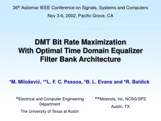
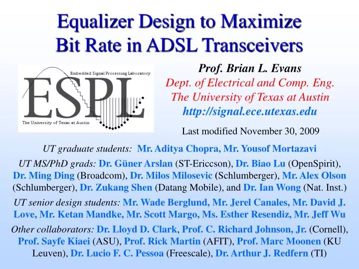
Equalizer Design to Maximize Bit Rate in ADSL Transceivers. Prof. Brian L. Evans Dept. of Electrical and Comp. Eng. The University of Texas at Austin http://signal.ece.utexas.edu. Last modified November 30, 2009. UT graduate students: Mr. Aditya Chopra, Mr. Yousof Mortazavi

E N D
Equalizer Design to MaximizeBit Rate in ADSL Transceivers Prof. Brian L. EvansDept. of Electrical and Comp. Eng.The University of Texas at Austinhttp://signal.ece.utexas.edu Last modified November 30, 2009 UT graduate students: Mr. Aditya Chopra, Mr. Yousof Mortazavi UT MS/PhD grads:Dr. Güner Arslan (ST-Ericcson), Dr. Biao Lu (OpenSpirit),Dr. Ming Ding (Broadcom), Dr. Milos Milosevic (Schlumberger), Mr. Alex Olson (Schlumberger),Dr. Zukang Shen (Datang Mobile), and Dr. Ian Wong (Nat. Inst.) UT senior design students:Mr. Wade Berglund, Mr. Jerel Canales, Mr. David J.Love, Mr. Ketan Mandke, Mr. Scott Margo, Ms. Esther Resendiz, Mr. Jeff Wu Other collaborators:Dr. Lloyd D. Clark, Prof. C. Richard Johnson, Jr. (Cornell), Prof. Sayfe Kiaei (ASU), Prof. Rick Martin (AFIT), Prof. Marc Moonen (KU Leuven), Dr. Lucio F. C. Pessoa (Freescale), Dr. Arthur J. Redfern (TI)
Introduction Digital Subscriber Line (DSL) Broadband Access Internet DSLAM Downstream(higher data rate) Service Provider DSL modem DSL modem Upstream VoiceSwitch LPF LPF Customer Premises Telephone Network DSLAM - Digital Subscriber Line Access Multiplexer LPF – Lowpass Filter (passes voiceband frequencies)
Introduction Discrete Multitone (DMT) DSL Standards ADSL – Asymmetric DSL Maximum data rates supported in G.DMT standard (ideal case) Echo cancelled: 14.94 Mbps downstream, 1.56 Mbps upstream Frequency division multiplexing (FDM): 13.38 Mbps downstream, 1.56 Mbps upstream Widespread deployment in US, Canada, Western Europe, and Hong Kong Central office providers only installing frequency-division multiplexed (FDM) ADSL:cable modem market1:2 in US & 2:1 worldwide ADSL+ 8 Mbps downstream min. ADSL2 doubles analog bandwidth VDSL – Very High Rate DSL Asymmetric Faster G.DMT FDM ADSL 2m subcarriers m [8, 12] Symmetric: 13, 9, or 6 Mbps Optional 12-17 MHz band 1997 2003 2003 2003 2005
Received bit stream Message bit stream Transmitter Channel Receiver Equalizer Outline • Multicarrier modulation • Conventional equalizer training methods • Minimum Mean Squared Error design [Stanford] • Maximum Shortening Signal-to-Noise Ratio design [Tellabs] • Maximum Bit Rate design (optimal) [UT Austin] • Minimum Inter-symbol Interference design (near-optimal) [UT Austin] • Per-tone equalizer [Catholic University, Leuven, Belgium] • Dual-path equalizer [UT Austin] • Conclusion
Multicarrier Modulation Single Carrier Modulation • Ideal (non-distorting) channel over transmission band • Flat magnitude response • Linear phase response: delay is constant for all spectral components • No intersymbol interference • Impulse response for ideal channel over all frequencies • Continuous time: • Discrete time: • Equalizer • Shortens channelimpulse response(time domain) • Compensates forfrequency distortion(frequency domain) nk g d(t-T) Channel Equalizer yk xk rk ek g d[k-D] w h + + + Training sequence - Ideal Channel Receiver generates xk g z- Discretized Baseband System
Multicarrier Modulation Multicarrier Modulation • Divide channel into narrowband subchannels • No inter-symbol interference (ISI) in subchannels if constant gain within every subchannel and if ideal sampling • Discrete multitone modulation • Baseband transmission • Based on fast Fourier transform (FFT) • Standardized for ADSL and VDSL sampled sinc pulse DTFT-1 w k -wc wc channel carrier magnitude subchannel frequency Subchannels are 4.3 kHz wide in ADSL and VDSL
complex-valued complex-valued real-valued Multicarrier Modulation Multicarrier Modulation by Inverse FFT Filter Bank g(t) x x Discrete time g(t) x x + + g(t) x x g(t) : pulse shaping filter Xi: ith subsymbol from encoder
Multicarrier Modulation Discrete Multitone Modulation Symbol • N/2 subsymbols are in general complex-valued • ADSL uses 4-level Quadrature AmplitudeModulation (QAM) during training • ADSL uses QAM of 22, 23, 24, …, 215 levelsduring data transmission • Multicarrier modulation using inverse FFT Quadrature Xi In-phase QAM X0 N-point Inverse FastFourierTransform x0 X1 x1 Mirror and conjugateN/2–1 complex subsymbols X2 x2 Yields one symbol of N real-valued samples XN/2 X2* xN-1 X1*
Multicarrier Modulation Discrete Multitone Modulation Frame • Frame is sent through D/A converter and transmitted • Frame is the symbol with cyclic prefix prepended • Cyclic prefix (CP) consists of last n samples of the symbol • CP reduces throughput by factor of • Linear convolution of frame withchannel impulse response • Is circular convolution if channel length is CP length plus one or shorter • Circular convolution frequency-domain equalization in FFT domain • Time-domain equalization to reduce effective channel length and ISI copy copy s y m b o li+1 CP CP s y m b o li v samples N samples
n+1 channel impulse response effective channel impulse response • : transmission delayn: cyclic prefix length Multicarrier Modulation Eliminating ISI in Discrete Multitone Modulation • Time domain equalizer (TEQ) • Finite impulse response (FIR) filter • Effective channel impulse response:convolution of TEQ impulse responsewith channel impulse response • Frequency domain equalizer (FEQ) • Compensates magnitude/phase distortionof equalized channel by dividing each FFTcoefficient by complex number • Generally updated during data transmission • ADSL G.DMT equalizer training • Reverb: same symbol sent 1,024 to 1,536 times • Medley: aperiodic pseudo-noise sequence of16,384 symbols for subchannel SNR estimation • Receiver returns numberof bits (0-15) to transmiteach subchannel i
ADSL Transceiver: Data Transmission Multicarrier Transceivers conventional ADSL equalizer structure 2.208 MHz N/2 subchannels N real samples S/P quadrature amplitude modulation (QAM) encoder mirror data and N-IFFT add cyclic prefix P/S D/A + transmit filter Bits 00110 TRANSMITTER each block programmed in lab and covered in one full lecture channel each block covered in one full lecture RECEIVER N/2 subchannels N real samples P/S time domain equalizer (FIR filter) QAM decoder N-FFT and remove mirrored data S/P remove cyclic prefix receive filter + A/D invert channel = frequency domain equalizer
Received bit stream Message bit stream Transmitter Channel Receiver Equalizer Outline • Multicarrier modulation • Conventional equalizer training methods • Minimum Mean Squared Error design [Stanford] • Maximum Shortening Signal-to-Noise Ratio design [Tellabs] • Maximum Bit Rate design (optimal) [UT Austin] • Minimum Inter-symbol Interference design (near-optimal) [UT Austin] • Per-tone equalizer • Dual-path equalizer • Conclusion
Conventional Equalizer Minimum Mean Squared Error TEQ Design nk TEQ Channel yk rk ek xk w h + + - b z- bk-D • Minimize E{ek2}[Chow & Cioffi, 1992] • Chose length of b (e.g. n+1) to shorten length of h * w • b is eigenvector of minimum eigenvalue of symmetricchannel-dependent matrix • Minimum MSE when where • Disadvantages • Does not consider bit rate • Deep notches in equalized frequency response Rxy is cross correlation matrix Why?
Conventional Equalizer Infinite Length MMSE TEQ Analysis • As TEQ length goes toinfinity, RD becomesToeplitz [Martin et al. 2003] • Eigenvector of minimumeigenvalue of symmetricToeplitz matrix has zeroson unit circle [Makhoul 1981] • Zeros of target impulseresponse b on unit circlekills n subchannels • Finite length TEQ plot • Each trace is a different zero of b • Distance of 32 zeros of b to unit circle averagedover 8 ADSL test channels for each TEQ length • Zeros cluster at 0.01 and 10-4 from UC for TEQ lengths 32 and 100 [Martin et al., 2004] Longer MMSE TEQ may be worse
w h n+1 channel impulse response effective channel impulse response Conventional Equalizer Maximum Shortening SNR TEQ Design • Minimize energy leakage outside shortened channel length • For each possible position of window[Melsa, Younce & Rohrs, 1996] • Equivalent to noise-free MMSE TEQ • Disadvantages • Does not consider channel noise • Does not consider bit rate • Deep notches in equalized frequency response (zeros of target impulse response near unit circle kill subchannels) • Requires Cholesky decomposition, which is computationally-intensive and does not allow TEQ lengths longer than cyclic prefix
nk rk yk xk h w + Conventional Equalizer Maximum Shortening SNR TEQ Design hwin, hwall : equalized channel within and outside the window • Objective function is shortening SNR (SSNR) • Choose w to minimize energy outside window of desired length Locate window to capture maximum channel impulse response energy Cholesky decomposition of B to find eigenvector for minimum generalized eigenvalue of A and B
Conventional Equalizer Modeling Achievable Bit Rate • Bit allocation bounded by subchannel SNRs: log(1 + SNRi / Gi) • Modelith subchannel SNR [Arslan, Evans & Kiaei, 2001] • Divide numerator anddenominator of SNRiby noise power spectral density Sn,i Used in Maximum Bit Rate Method Used in Minimum ISI Method Conventional subchannel SNRi
qiH Sx,i H HT qi Ai = Sn,i Sx,i qiH qiH H HT qi = qi Bi + D GT G DT FT F Conventional Equalizer Maximum Bit Rate (MBR) TEQ Design • Subchannel SNR as nonlinear function of equalizer taps w • Maximize nonlinear function of bits/symbol with respect to w • Good performance measure for comparison of TEQ design methods • Not an efficient TEQ design method in computational sense qiis ith row of DFT matrix Fractional bits for optimization
Conventional Equalizer Minimum-ISI (Min-ISI) TEQ Design • Rewrite subchannel SNR[Arslan, Evans & Kiaei, 2001] • Generalize MSSNR method by weighting ISI in frequency • Minimize frequency weightedsum of subchannel ISI power • Penalize ISI power in high conventional SNR subchannels: • Constrain signal path gain to oneto prevent all-zero solution for w • Solution is eigenvector of minimum generalized eigenvalue of X and Y • Iterative Min-ISI method [Ding et al. 2003] • Avoids Cholesky decomposition by using adaptive filter theory • Designs arbitrary length TEQs without loss in bit rate • Overcomes disadvantages of Maximum SSNR method ISI power weighted in frequency domain by inverse of noise spectrum
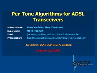
Received bit stream Message bit stream Transmitter Channel Receiver Equalizer Outline • Multicarrier modulation • Conventional equalizer training methods • Minimum Mean Squared Error design • Maximum Shortening Signal-to-Noise Ratio design • Maximum Bit Rate design (optimal) • Minimum Inter-symbol Interference design (near-optimal) • Per-tone equalizer [Catholic University, Leuven, Belgium] • Dual-path equalizer • Conclusion
N realsamples N/2 complex samples invert channel = frequency domain equalizer N-FFT and remove mirrored data S/P time domain equalizer (FIR filter) remove cyclic prefix Per-Tone Equalizer Drawbacks to Using Single FIR Filter for TEQ • Conventionalequalizer • Equalizes all tones in combined fashion: may limit bit rate • Output of conventional equalizer for tone i computed using sequence of linear operations Zi = Di rowi(QN ) Yw Di is the complex scalar value of one-tap FEQ for tone i QN is the NN complex-valued FFT matrix Y is an NLw real-valued Toeplitz matrix of received samples w is a Lw1 column vector of real-valued TEQ taps Y w represents convolution
Sliding N-Point FFT (Lw-frame) N+n z-1 W1,0 W1,1 W1,2 W1,Lw-1 N + Lw – 1channels z-1 N+n WN/2,0 WN/2,1 WN/2,2 WN/2,Lw-1 z-1 FEQ is a linear combinerof up to N/2 Lw-tap FEQs y N+n Per-Tone Equalizer Frequency-Domain Per Tone Equalizer • Rewrite equalized FFT coefficient for each of N/2 tones[Van Acker, Leus, Moonen, van de Wiel, Pollet, 2001] Zi = Di rowi(QN ) Yw = rowi(QNY) ( wDi ) = rowi(QNY) wi • Take sliding FFT to produce NLw matrix product QN Y • Design wi for each tone
Received bit stream Message bit stream Transmitter Channel Receiver Equalizer Outline • Multicarrier modulation • Conventional equalizer training methods • Minimum Mean Squared Error design • Maximum Shortening Signal-to-Noise Ratio design • Maximum Bit Rate design (optimal) • Minimum Inter-symbol Interference design (near-optimal) • Per-tone equalizer • Dual-path equalizer [UT Austin] • Conclusion
Path Selection for each Subchannel TEQ 1 FFT FEQ TEQ 2 FFT Dual-Path Equalizer Dual-Path Time Domain Equalizer (DP-TEQ)[Ding, Redfern & Evans, 2002] • First FIR TEQ equalizes entire available bandwidth • Second FIR TEQ tailored for subset of subchannels • Subchannels with higher SNR • Subchannels difficult to equalize, e.g. at boundary of upstream and downstream channels in frequency-division multiplexed ADSL • Minimum ISI method is good match for second FIR TEQ • Path selection for each subchannel is fixed during training • Up to 20% improvement in bit rate over MMSE TEQs • Enables reuse of VLSI designs of conventional equalizers
Simulation Results Simulation Results for 17-Tap Equalizers Parameters Cyclic prefix length 32 FFT size (N) 512 Coding gain (dB) 4.2 Margin (dB) 6 Input power (dBm) 23 Noise power (dBm/Hz) -140 Crosstalk noise 24 ISDN disturbers Bit rate (Mbps) Downstream transmission Carrier serving area (CSA) test loop Figure 1 in [Martin, Vanbleu, Ding, Ysebaert, Milosevic, Evans, Moonen & Johnson, Oct. 2005] UNC(b) means unit norm constraint on target impulse response b, i.e. || b || = 1 MDS is Maximum Delay Spread design method [Schur & Speidel, 2001]
Simulation Results Simulation Results for 17-Tap Equalizers Parameters Cyclic prefix length 32 FFT size (N) 512 Coding gain (dB) 4.2 Margin (dB) 6 Input power (dBm) 23 Noise power (dBm/Hz) -140 Crosstalk noise 24 ISDN disturbers Bit Rate (Mbps) Downstream transmission Carrier Serving Area (CSA) Test Loop Figure 3 in [Martin, Vanbleu, Ding, Ysebaert, Milosevic, Evans, Moonen & Johnson, Oct. 2005] MDR is Maximum Data Rate design method [Milosevic et al., 2002] BM-TEQ is Bit Rate Maximizing design method [Vanbleu et al., 2003] PTEQ is Per Tone Equalizer structure and design method [Acker et al., 2001]
Simulation Results Estimated Computational Complexity Computational Complexity in 10 log10(MACs) Equalizer Design Algorithm MAC means a multiplication-accumulation operation
Simulation Results Bit Rate vs. Training Complexity Tradeoffs Bit Rate (Mbps) Training Complexity in log10(MACs) MAC means a multiplication-accumulation operation
Simulation Results Achievable Bit Rate vs. Delay Parameter Bit rate (Mbps) Delay Parameter D for CSA Test Loop 4 Large plateau of near-optimal delays (optimal choice requires search)One choice is to set the delay parameter equal to cyclic prefix length
Conclusion Contributions by Research Group • New methods for single-path time-domain equalizer design • Maximum Bit Rate method maximizes bit rate (upper bound) • Minimum Inter-Symbol Interference method (real-time, fixed-point) • Minimum Inter-Symbol Interference TEQ design method • Generalizes Maximum Shortening SNR by frequency weighting ISI • Improve bit rate in an ADSL transceiver by change of software only • Implemented in real-time on three fixed-point digital signal processors:Motorola 56000, TI TMS320C6200 and TI TMS320C5000 • New dual-path time-domain equalizer • Achieves bit rates between conventional and per tone equalizers • Lower implementation complexity in training than per tone equalizers • Enables reuse of ASIC designs http://www.ece.utexas.edu/~bevans/projects/adsl
Conclusion UT Austin Matlab DMTTEQ Toolbox 3.1 • Single-path, dual-path, per-tone & TEQ filter bank equalizers Available at http://www.ece.utexas.edu/~bevans/projects/adsl/dmtteq/ 18 design methods default parameters from G.DMT ADSL standard 23 -140 different graphical views variousperformance measures
Conclusion UT Austin ADSL2 Simulator 1.1 • Simulation controls • Simulation state indicator • Description window • Simulation parameters • Performance indicators http://users.ece.utexas.edu/~bevans/projects/adsl/simulator/index.html
Introduction Applications of Broadband Access Residential Business
Introduction Selected DSL Standards Courtesy of Shawn McCaslin (National Instruments, Austin, TX)
Decoder Message Sink Message Source Encoder Noise Modulator Channel Demodulator Receiver Transmitter Introduction A Digital Communications System • Encoder maps a group of message bits to data symbols • Modulator maps these symbols to analog waveforms • Demodulator maps received waveforms back to symbols • Decoder maps the symbols back to binary message bits
2.1 1.7 1 1 1 1 1 1 .7 .7 .4 .1 = * Receivedsignal Channelimpulseresponse -1 Transmitted signal Threshold at zero 1 1 1 1 1 Detected signal Introduction Intersymbol Interference (ISI) • Ideal channel • Impulse response is impulse • Flat frequency response • Non-ideal channel • Causes ISI • Channel memory • Magnitude and phasevariation • Received symbol is weightedsum of neighboring symbols • Weights are determined by channelimpulse response
MMSE equalizer frequency response Zero-forcing equalizer frequency response Channel frequency response Introduction Combat ISI with Equalization • Equalization because channel response is not flat • Zero-forcing equalizer • Inverts channel • Flattens freq. response • Amplifies noise • MMSE equalizer • Optimizes trade-offbetween noiseamplification and ISI • Decision-feedbackequalizer • Increases complexity • Propagates error
Introduction Cyclic Prefix Repeated symbol cyclic prefix * to be removed = equal
Multicarrier Modulation Open Issues for Multicarrier Modulation • Advantages • Efficient use of bandwidth without full channel equalization • Robust against impulsive noise and narrowband interference • Dynamic rate adaptation • Disadvantages • Transmitter: High signal peak-to-average power ratio • Receiver: Sensitive to frequency and phase offset in carriers • Open issues • Pulse shapes of subchannels (orthogonal, efficient realization) • Channel equalizer design (increase bit rate, reduce complexity) • Synchronization (timing recovery, symbol synchronization) • Bit loading (allocation of bits in each subchannel) • Echo cancellation
Conventional Equalizer TEQ Algorithm • ADSL standards • Set aside 1024 frames (~.25s) for TEQ estimation • Reserved ~16,000 frames for channel and noise estimation for the purpose of SNR calculation • TEQ is estimated before the SNR calculations • Noise power and channel impulse response can be estimated before time slot reserved for TEQ if the TEQ algorithm needs that information
Conventional Equalizer Single-FIR Time-Domain Equalizer Design Methods • All methods below perform optimization at TEQ output • Minimizing the mean squared error • Minimize mean squared error (MMSE) method [Chow & Cioffi, 1992] • Geometric SNR method [Al-Dhahir & Cioffi, 1996] • Minimizing energy outside of shortened (equalized) channel impulse response • Maximum Shortening SNR method [Melsa, Younce & Rohrs, 1996] • Divide-and-conquer methods [Lu, Evans, Clark, 2000] • Minimum ISI method [Arslan, Evans & Kiaei, 2000] • Maximizing bit rate [Arslan, Evans & Kiaei, 2000] • Implementation • Geometric SNR is difficult to automate (requires human intervention) • Maximum bit rate method needs nonlinear optimization solver • Other methods implemented on fixed-point digital signal processors
nk yk rk ek xk w h + + - b z- bk-D Conventional Equalizer Minimum Mean Squared Error (MMSE) TEQ O selects the proper part out of Rx|y corresponding to the delay
Conventional Equalizer Near-optimal Minimum-ISI (Min-ISI) TEQ Design • Generalizes MSSNR method by frequency weighting ISI • ISI power in ith subchannel is • Minimize ISI power as a frequency weighted sum of subchannel ISI • Constrain signal path gain to one to prevent all-zero solution • Solution is a generalized eigenvector of X and Y • Possible weightings • Amplify ISI objective function in subchannels with lownoise power (high SNR) to put ISI in low SNR bins: • Set weighting equal to input power spectrum: • Set weighting to be constant in all subchannels (MSSNR): • Performance virtually equal to MBR (optimal) method
Conventional Equalizer Efficient Implementations of Min-ISI Method • Generalized eigenvalue problem can solved with generalized power iteration: • Recursively calculate diagonal elements of X and Y from first column [Wu, Arslan, Evans, 2000]
Conventional Equalizer Motivation for Divide-and-Conquer Methods • Fast methods for implementing Maximum SSNR method • Maximum SSNR Method • For each , maximum SSNR method requires • Multiplications: • Additions: • Divisions: • Exhaustive search for the optimal delay • Divide LwTEQ taps into (Lw - 1) two-tap filters in cascade • Design first two-tap filter then second and so forth (greedy approach) • Develop heuristic to estimate the optimal delay
Conventional Equalizer Divide-and-Conquer Approach • The ith two-tap filter is initialized as either • Unit tap constraint (UTC) • Unit norm constraint (UNC) • Calculate best gi or i by using a greedy approach either by • Minimizing (Divide-and-conquer TEQ minimization) • Minimizing energy in hwall (Divide-and conquer TEQ cancellation) • Convolve two-tap filters to obtain TEQ
Conventional Equalizer Divide-and-Conquer TEQ Minimization (UTC) • At ith iteration, minimize Ji over gi • Closed-form solution
Conventional Equalizer Divide-and-Conquer TEQ Minimization (UNC) • At ith iteration, minimize Ji over i • where Calculate i in the same way as gi for UTC version of this method
Conventional Equalizer Divide-and-Conquer TEQ Cancellation (UTC) • At ith iteration, minimize Ji over gi • Closed-form solution for the ith two-tap FIR filter