Download
1 / 55
590 likes | 649 Views
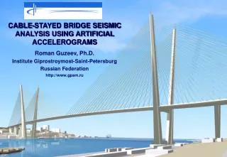
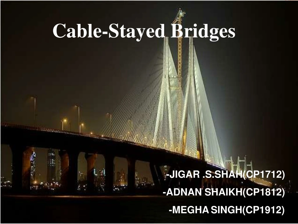
Cable-Stayed Bridges. -JIGAR .S.SHAH(CP1712) -ADNAN SHAIKH(CP1812) -MEGHA SINGH(CP1912). D IFFERENCE BETWEEN CABLE STAYED BRIDGE AND CABLE SUSPENSION BRIDGE. A multiple-tower cable-stayed bridge may appear similar to

E N D
Cable-StayedBridges -JIGAR.S.SHAH(CP1712) -ADNAN SHAIKH(CP1812) -MEGHASINGH(CP1912)
DIFFERENCE BETWEEN CABLE STAYED BRIDGE AND CABLE SUSPENSIONBRIDGE • A multiple-tower cable-stayed bridge may appear similarto • a suspension bridge, but in fact is very different in principle andin • the method ofconstruction. • In the suspension bridge, a large cable hangs between twotowers, and is fastened at each end toanchoragesin the ground or to a massivestructure. • These cables form the primary load-bearing structure for the bridge deck. Before the deck is installed, the cables are undertensionfrom only their ownweight. • Smaller cables or rods are then suspended from the main cable,and used to support the load of the bridge deck, which is lifted in sections and attached to the suspendercables. • The tension on the cables must be transferred to the earth bythe anchorages, which are sometimes difficult to construct owingto poor soilconditions.
ADVANTAGES OF CABLE STAYEDBRIDGES • much greater stiffness than the suspension bridge, sothat deformations of the deck under live loads arereduced • can be constructed by cantilevering out from the tower - the cables act both as temporary and permanentsupports to the bridgedeck • for a symmetrical bridge (i.e.spanson either side ofthe tower are the same), the horizontal forces balance and largeground anchoragesare notrequired.
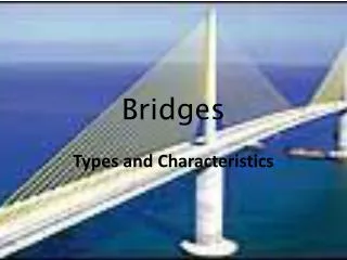
INTRODUCTION • A cable-stayed bridge, one of the most modern bridges, consists of a continuous strong beam (girder) with oneor more pillars or towers in themiddle • Cables stretch diagonally between these pillars ortowers and the beam .These cables support thebeam • The cables are anchored in the tower rather than atthe end
LOAD TRANSMISSION slab Tension Cables pylons Pilecap Compression piles 5 soil
CLASSIFICATIONS • Basedon arrangements of thecables • Radiating • Harp • Fan • star • Based on the shape ofpylon • A-type • H-type • Y-type 7
CLASSIFICATIONS radial : cables connect evenly throughout the deck, but all converge on the top of thepier harp : cables are parallel, and evenly spaced along the deck and thepier fan : a combination of radial and harptypes star-shaped : cables are connected to two opposite points on thepier
9 SHAPES OFPYLON
CABLE • A cable may be composed of one or more structural ropes, structural strands, locked coil strands or parallel wirestrands. • A strand is an assembly of wires formed helically around centre wire in one or more symmetricallayers. • A strand can be used either as an individual load-carrying member, where radius or curvature is not a major requirement, or as a component in the manufacture of the structuralrope. • A rope is composed of a plurality of strands helically laid around a core. In contrast to the strand, a rope provides increased curvature capability and is used where curvature of the cable becomes an importantconsideration. 10
Cables are made of high-strength steel, usually encased in a plastic or steel covering that is filled with grout , a finegrained form of concrete, for protection againstcorrosion.
SELECTION OF CABLECONFIGURATION • The selection of cable configuration and number of cables is dependent mainly on length of the span, type of loadings, number of roadway lanes, height of towers, and the designer’s individual sense of proportion and aesthetics. • Cost also plays important role in deciding theselection. • Using less number of cables increases concentrated load at a single point thereby requiring additional reinforcement for the deck slab as well as pylon. 13
POSITIONS OF THE CABLES INSPACE • Two planesystem • Two Vertical PlanesSystem • Two Inclined PlanesSystem • The Single PlaneSystem 14
Two Vertical PlanesSystem • In this type of system there are two parallel sets of cables and the tower on the either sides of the bridge, which lie in the same verticalplane. • The cable anchorages may be situated outside the deck structure, which is better than the other in terms of space as no deck area of the deck surface is obstructed by the presence of the cables and the towers. • but this requires substantial cantilevers to be constructed in order to transfer the shear and the bending moment into the deck structure. 15
When the cables and tower liewithinthe cross-section ofthe bridge, the area taken up cannot be utilized as a part of the roadway and may be only partly used for the sidewalk. Thus as area of the deck surface is made non-effective andhasto be compensated for by increasing overall width of thedeck. 16
TWO INCLINED PLANESSYSTEM • In this system the cables run from the edges of the bridge deck to a point above the centreline of the bridge on an A-shaped tower or λ- shaped or diamond shapedpylon. • This arrangement can be recommended for very long spans where the tower has to be very high and needs the lateral stiffness given by the triangle and the framejunction. 17
THE SINGLE PLANESYSTEM • This type of system consists of bridges with only one vertical plane of stay cables along the middle longitudinal axis of the superstructure • As the cables are located in a single centre vertical strip thus all the space is utilized by thetraffic. • This system also creates a lane separation as a natural continuation of the highway approaches to thebridge. • longitudinal arrangements of the cables used with two planes bridges are also applied to single centre girderbridges. 18
BRIDGEDETAILS: • LENGTH OF SEA LINK: 5600m • LENGTH OF CABLESTAYPORTION: 600m • HEIGHT OF PYLON/TOWER : 123m • NO. OF PIERS :620 • LONGEST SPAN : 2x250m • LOCATION : A CLOVERLEAF INTERCHANGE AT MAHIM INTERSECTION AND A FLYOVER AT THE LOVEGROVE INTERSECTION HAVE BEEN PROPOSED AS PART OF THIS PROJECT TO ENHANCE THE FASTER AND SAFE TRAFFIC DISPERSAL. • CLIENT :MSRDC • MAIN CONTRACTOR :HCC • TOTAL PROJECT COST : Rs 850CRORE • SCHEDULED INITIALIZATION &COMPLETION: • MAY, 1999 & MAY,2002 • ACTUAL COMPLETION : AUGUST,2009 • AMOUNT OF CONC. USED : 0.2 millioncum. 22
SUB SURFACEEXPLORATION • INITIAL GEOTECHNICALINVESTIGATION 25 BORE HOLES ALONG THE LENGTH TO OBTAIN THE SOIL PROFILE. 23
SUB STRUCTURECONSTRUCTION • PILING: • TYPE OF PILES : COMBINED END EARING AND FRICTIONPILES • DIA OF PILES USED : 1.5 – 2m • DEPTH OF PILES : 5.15 – 663.4m • PILE GROUP UNDER THE PYLON : 40NOS. • CONST. TYPE : BORED CAST IN SITU • TECHNOLOGY USED : REVERSECIRCULATION • DRILL • SUPPORT STRUCTURES : COFFERDAM &SHEET • PILING • PILE CAP THK – 3.5m • CONCRETE USED – M60,HPC • PIER LENGTH – 4-6 m DEPENDING UPON THE GRADIENT OFBED 24
F COFFER DAMCONSTRUCTION • A TEMPORARY WATER TIGHT STRUCTURE TO FACILITATE CONST. OF PROJECT WHICH ARE SUBMERGED INWATER. • IT CONSIST OF CASINGSO 1.5 m DIA AND SHEETPILES 26
PILING • ONCE THE COFFER DAMIS CONSTRUCTED, WATER IS PUMPED OUT. • DEWATERINGTECHNIQUE ADOPTED WAS WELL POINTSYSTEM. • PILING TECHNIQUEUSED WAS REVERSE CIRCULATION DRILL. • IN THIS METHOD,PRECAST SEGMENT IS PLACEDON • SOIL & DRILLING ISDONE WITH DRILLBIT • 27
RCD DRILLBIT • DRILL BIT CONSISTSOF PNEUMATICPISTON • DEPTH ACHIEVABLE :500 m • BIT DIA : 13 – 20cm • MATERIAL :TUNGSTEN • STEEL • OUTPUT : 900 – 1150cfm @350 RPM 28
LOWER PLYONCONSTRUCTION LOWER PYLON CONSISTS OF : PIERTABLE LOWER PIERLEGS CONST. METHOD USED : SELF CLIMBINGFORM CONST. CONST. IS DONE IN LIFTS. 6 LIFTS REQUIRED FOR CONST OF LOWERPYLON. 33
UPPERPYLON WHILE CONSTRUCTING THE UPPER TOWER LEG, THE CARE WAS TO BE TAKEN THAT THE REINFOCEMENT DOESNOTFALL DUE TO ITS SELF WEIGHT, THAT IS WHY EMBEDDED TUBES WERE FIT IN JUMP FORM TOPROVIDE EXTRA SUPPORT INLEGS. 35
CABLE STAYEDBRIDGE SUPERSTRUCTURE CONSTRUCTION 41
SUPERSTRUCTURECONSTRUCTION • Precast Segmental Constructioninvolving • MatchCasting • Span by Span Erection for approachspans • Parameters for segmentcasting • Alignment of the individual span to whichsegment belong. • Precamber necessary to take care of deformationsof the girder due to self weight, prestress and other permanentloads. • Necessary corrections for errors in the castingof • adjacent segment cast earlier, while matchcasting. 42
CASTINGYARD PLAN of CastingYard 43
CASTINGYARD • Total number of segments – 2500 &more. • Three types ofsegment • Approach Span Segment • Main Cable stayedsegment • Segment onPiers • Size of Approach Segment –18.1m x 3.2m x3.0m • Size of Main Cable Stay Segment – 20.8m x 3.2m x3m • Weight of each Segment – 150tonnes • Total lengthofCasting Yard-350m • Capacity – 300 segments at atime 44
45 Segments placed in CastingYard
ERECTION OFSEGMENTS • The Erection Gantry does the erection ofspan. • A typical 50m span comprises of 15 numbersof precastsegments 46
The segments are transported to the site with the helpof barges. • Each segment is lifted and all the segments in a single span are aligned together and brought about at thesame level. 47
At the time of match casting High Tensile Steel Rodsare passed through the ducts provided in the segments and tightened with the help of a Winchmachine. • Neutobond BC solution is used so that the twosegments can be alignedtogether. 48
I Asian Hercules used to displace ErectionGantry 49