Download
1 / 26
320 likes | 870 Views
Chapter 7. DIFFUSION Part 1 . Dr. Wanda Wosik ECE 6466, F2012. DIFFUSION Processes . • Doping profiles determine many short-channel characteristics in MOS devices. • Resistance impacts drive current. • Scaling implies all lateral and vertical dimensions scale by the same factor.

E N D
Chapter 7 DIFFUSION Part 1 Dr. Wanda Wosik ECE 6466, F2012
DIFFUSION Processes • Doping profiles determine many short-channel characteristics in MOS devices. • Resistance impacts drive current. • Scaling implies all lateral and vertical dimensions scale by the same factor. • Generally doping levels need to increase and xJ values need to decrease.
Concept of Sheet Resistance of Doped Layers. • The resistivity of a cube is given by W t • The sheet resistance of a shallow junction is L Resistivity Sheet resistance • For a non-uniformly doped layer, L/W=# squares I12 V34 1 2 I23 V41 NB Numerically integrated by Irvin for simple analytical profiles (later). 4 Raverage 3 • Sheet resistance s[Ω/sq.] can be experimentally measured by a four point probe technique orvan der Pauw. • Doping profiles can be measured by SIMS (chemical) or spreading R (electrical). In MOSFETs In MOSFETs Rcontact + Rsource + Rext < 10% Rchen s but keep xj small to avoid DIBL (conflicting requirements
VSLS: Shallow and Heavily Doped Junctions 50 nm LDD cannot be used
Historical Development and Basic Concepts 1960 • Development (40 years) in predeposition • Solid-phase diffusion from glass layer. • Gas phase deposition at high temperatures (B2H6, PH3, AsH6) reproducibility; good only for solid sol. (too high Ns) • Replace predeposition by ion implantation; good for bigger devices but difficult for small ones (TED) • Return to diffusion for deep submicron devices
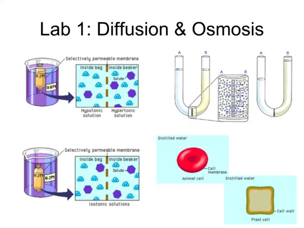
Diffusion Concepts • • Diffusion is the redistribution of atoms • from regions of high concentration of • mobile species to regions of low • concentration. It occurs at all temperatures, • but the diffusivity has an exponential • dependence on T. • Predeposition: doping often proceeds by • an initial predep step to introduce the • required dose of dopant into the substrate. • Drive-In: a subsequent drive-in anneal • then redistributes the dopant giving the • required xJ and surface concentration.
Dopant Solid Solubility Metastable electrical activation (search for metastable annealing?) • • Dopants are soluble in bulk silicon up to a maximum value before they precipitate into another phase. • Concentrations above SS limits result in inactive complexes (defects, precipitates) Practical concentrations for active P and As • Dopants may have an “electrical” solubility that is different than the solid solubility defined above. • One example - As4V - electrically inactive complex. As complexes not active electrically
Diffusion from a Microscopic Viewpoint • Macroscopic dopant redistribution is described by Fick’s first law, which describes how the flux (or flow) of dopant depends on the doping gradient. • D is the diffusivity (cm2 sec-1). D is isotropic in the silicon lattice. • Fick’s second law describes how the change in concentration in a volume element is determined by the fluxes in/out of the volume. D = const. D=f(N): • If D is a constant this gives D = const • This is rarely true in practice but this is the only form of Fick's second law, which can be solved analytically.
Analytic Solutions Of Fick’s Laws Limited Source: Consider a fixed dose Q, introduced as a delta function at the origin. • The solution that satisfies Fick’s second law is • In steady state ( ) ≠f(t) -epi layer: Ion implant Very short diffusion Boundary conditions • Important consequences: 1. Dose Q remains constant 2. Peak concentration decreases as 3. Diffusion distance increases as Dose C with √time L=2√(Dt) Diffusion length
Analytic Solutions Of Fick’s Laws Gaussian Solution near a Surface 2. Constant Source Near A Surface: • This is similar to the previous case except the diffusion only goes in one direction. Assume no dopant is lost at the surface Delta layer’s thickness << X = 2 √(Dt) (final penetration) At the surface, if oxide growth occurs dopant segregation; evaporation
Error Function Solution in an Infinite Medium 3. Infinite Source (unlimited supply): • The infinite source is made up of small slices each diffusing as a Gaussian. Linear superposition ∑xi ∆x0 • The solution which satisfies Fick’s second law is Deposited layer t Complementary error function
Error Function Solution in an Infinite Medium • Important consequences of error function solution: • Symmetry about mid-point allows solution for constant surface concentration to be derived. • Error function solution is made up of a sum of Gaussian delta function solutions. • Dose beyond x = 0 continues to increase with annealing time. (See Appendix A.9 in text for properties of erfc.) 4. Constant Surface Concentration: • Just the right hand side of the above figure. Erfc function - Tabulated or approximated • Note that the dose is given by
Error – Function Solution Near a Surface Surface concentration set! by the solubility limits of the dopants CS(T) Linear scale Log scale Qerfc increases with time. Qgauss is constant in time; it is set by a predeposition (erfc) preceding the diffusion (drive-in)
Intrinsic Dopant Diffusion Coefficients • Intrinsic dopant diffusion coefficients are found to be of the form: (13) EA activation energy • Note that ni is very large at process temperatures, so "intrinsic" actually applies under many conditions. • Note the "slow" and "fast" diffusers. Solubility is also an issue in choosing a particular dopant. Intrinsic Diffusion means that Ndopant < ni @ diffusion T 1000 °C, ni = 7.14 * 1018cm-3 (1.45 * 1010 cm-3@ RT). Arrhenius fit Eg/2kT Fast Diffusers Slow Diffusers
Intrinsic Diffusion Coefficients of Dopants in Silicon Arrhenius fit @ High dopant concentrations the diffusion is enhanced.
Effect Of Successive Diffusions • If a dopant is diffused at temperature T1 for time t1 and then is diffused at temperature T2 for time t2, the total effective Dt is given by the sum of all the individual Dt products. • The Gaussian solution only holds if the Dt used to introduce the dopant is small compared with the final Dt for the drive-in; i.e. if an initial delta function approximation is reasonable. • Example: In a bipolar transistor, if the emitter profile is formed by a predep and the base profile by an implant + drive-in, then the junctions occur where: (Emitter Dt) (Base+EmitterDt i.e. Dteff)
Successive Diffusion Steps Dt is a measure of thermal budget @ one T: T1 followed by T2: Equivalent time Transient Enhanced Diffusion (TED) and Concentration Enhanced Diffusion (CED) when D increases with C and/or crystallographic/point defects Use: Computer Simulation includes diffusion enhancement Wolf, VLSI Era
Design Of Diffused Layers • Eqn. (3) has been numerically integrated for specific cases (erfc and Gaussian). • Example of Irvin’s curves, in this case for P type Gaussian profiles. (Other examples are in Appendix A.8 in the text.) Important: Rs, Cs, xj Surface Concentration determined from Rs (= s) and xj measurements Irvin’s curves for erfc and Gaussian profiles
Design and Evaluation of Diffused Layer • We can now consider how to design a boron diffusion process (say for the well or tub of a CMOS process - Figs. 2.10 - 2.12), such that: { Example: Design a B diffusion processs=900/sq., xj = 3 µm for substrate CB= 1015 cm-3 Pick 1100 °C D=1.5 * 10-13 cm2sec-1 t = 6.8 hour (ex.: the well process) Use: Q=C(0,t)(Dt)1/2=4.3*1013 cm-2implanted or predeposition (initial dose) From predeposition@ 950 °C, Csol.sol=2.5*1020cm-3, D=4.2*1015 cm2sec-1 – not valid since Cs_predeposition>>ni Delta function approx. Dtpredep=2.3*10-14<< Dtdrivein=3.7*10-9 So Gaussian distribution is correct for the drive-in process
(More of the step by step approach) • The average conductivity of the layer is • From Irvin’s curve we obtain • We can surmise that the profile is Gaussian after drive-in. so that • If the drive-in is done at 1100 ˚C, then the boron diffusivity is • The drive-in time is therefore
Measurement Methods SIMS – Secondary Ion Mass Spectroscopy – sensitivity 1016 –1017 cm-3. Analysis of chemical concentration of dopants (both active and non active) Mass analyzed and counted C(X) Test areas may be included on an IC wafer As, P, Sb bombarded with Cs as primary ions produce dopant ions. Required: high ion yield, small mass interference. Problems with shallow junctions if Cs used – knock-on. Oxygen – noise floor B, In O (oxygen) Problems: • “Knock on” – incident beam recoils atoms into the substrate ( with ion mass Cs>O degrades depth resolution) • Sputtering rate at the surface increased by oxide use lower energies down to 200 eV- 5keV to decrease sputtering (important for shallow junctions) • Multilayer structures show matrix effect (sputtering yield and ion yield) and mixing (heavy Cs) • Use oxygen bleed – keep ionization yield constant.
Manufacturing Methods and Equipment Furnaces: horizontal, vertical (100 °C/min ramp) Temperatures: 800-1100 °C, N2 (+O2 low ) or Ar, O2 when oxide must be grown So with T (but can it be ignored during ramping?) 750-800 °C@ 5-10°C/min to 1000-1100 °C (warpage) For TED defects induced by implantation show D at low T than at high T. • RTAgoal: no diffusion but damage annealing/dopant activation Issues: • 100 °C/sec ramp • Single wafer processing. • 1-100 sec process. • Wafer T and uniformly measurement and control.
Spreading Resistance R(x) (x) n(x) Compare with C(x) from SIMS to get dopant activation. (information on defects, clusters etc.) 8’- 34’ SIMS R From Wolf, VLSi Era x junction
Sheet resistance Four point probe. (Figure 3.12); for shallow junctions use the Van De Pauw structure Capacitance Voltage C-V of a MOS Capacitor C XD(V) xD(N) N(x) TEM Cross Section Preparation of samples: Very complex Delineation by etching the doped silicon in HF: HNO3:CH3COOH 1 : 40 : 20 Doped silicon etch rate depends on dopant concentrations
2D Electrical Measurements Using Scanning Probe Microscopy Random distribution depends on the doping concentrations 1.3nm @ 1020 cm-3, 6.2 nm @ 1018 cm-3, 28.8 nm@ 1016 cm-3 STM – Scanning Tunneling Microscopy not useful scanning capacitance (from STM or rather AFM) and Scanning Resistance. Problems: Cross-Section=preparation hard, Image interpretation (CN) For soft contact Oxide on Scanning resistance - as in SRP but better control of the probes (cantilever) Inverse Electrical Measurements I-V, C-V of devices may not match simulated characteristics make corrections as to the doping profiles.