Download
1 / 1
10 likes | 120 Views
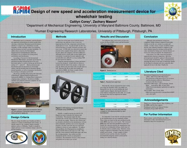
Design of new speed and acceleration measurement device for wheelchair testing. Caitlyn Corey 1 , Zachary Mason 2 1 Department of Mechanical Engineering, University of Maryland Baltimore County, Baltimore, MD 2 Human Engineering Research Laboratories, University of Pittsburgh, Pittsburgh, PA.

E N D
Design of new speed and acceleration measurement device for wheelchair testing Caitlyn Corey1, Zachary Mason21Department of Mechanical Engineering, University of Maryland Baltimore County, Baltimore, MD 2Human Engineering Research Laboratories, University of Pittsburgh, Pittsburgh, PA Methods Results and Discussion Conclusion Introduction Wheelchair speed, acceleration, and deceleration are important considerations for many people when selecting a wheelchair. Maximum speed determines whether it is legal to use a wheelchair on roads, footpaths, or both, and high values of acceleration and deceleration can lead to postural instability. To address these concerns, the International Organization for Standardization (ISO) has developed a set of standards for testing speed, acceleration, and deceleration. According to Section 6 of the International Standard for Wheelchairs, maximum speed must be measured traveling forward and in reverse on a horizontal surface, as well as driving up and down an incline of 3° and of 6°. Both acceleration and deceleration must be measured on a horizontal surface, and deceleration must be measured during normal operation, as well as emergency deceleration by reversing or emergency power-off. The device currently being used at the University of Pittsburgh’s Human Engineering Research Laboratories (HERL) is a trailing wheel connected to a laptop using a serial port. The device is bulky, outdated, uses batteries and most computers do not come standard with a serial port. Since two of the main issues with the current system were size and ease of use, it was very important that all of the components selected were small and easy to use. An optical shaft encoder was selected because it is small, extremely accurate, and easy to use. A USB cable was selected to connect the encoder to the computer being used to collect data, because almost all computers now have USB ports. Although wireless would make testing slightly more convenient, it would also be more expensive and considerably more difficult to set up, making USB the more practical solution. Using the selected hardware, a frame and wheel system was designed. A shaft with two wheels is coupled with the shaft of the encoder, so that each time the wheels turn, the shaft of the encoder turns as well. Because the device parts were made and assembled at HERL, the frame is made of three separate pieces, joined by screws. Figure 2. CAD drawing of proposed design, developed using SolidWorks Initially, a sample program provided by US Digital was used to measure the velocity and acceleration. This program inputs the data, calculates the velocity and acceleration, and displays the velocity on a gauge. However, the velocity and acceleration calculated are the instantaneous velocity and acceleration, and there was a severe lag in the program. In many cases this lag even caused the computer to freeze or cash completely. To address these problems, the C# program was modified to simply read the data in and write it to a file. This data file is then opened in MATLAB using code from the existing program. Any outliers are then eliminated, and the velocity at each point is calculated. The maximum velocity is then selected and printed out in meters per second. Two different chairs were used to test the new system: the Rascal 600T scooter and the Permobil c500 power wheelchair.. Figure 3. Testing set up Table 1. Results from each trial Note that the velocity measured for trial 3 of the tests using the Permobil c500 is incredibly low. During this test, the set screws holding the shaft coupler in place slipped, allowing the wheels to rotate without rotating the encoder shaft. As a result, the data for this trial was neglected for further calculations. Table 2. average velocities and how they compare to the values provided by each manufacturer It is important to note that the velocities provided by the manufacturers are not completely reliable. These values are based on the mass produced model, while HERL may have a test version. The version at HERL may also have been modified in some way. Finally, the value provided by the manufacturer may be based on recommended settings, which may not be what the chair is actually using. Therefore, more testing is required to determine if the new system is reliable and accurate. A larger sample of chairs should be tested, and the velocities should be measured both using the current system and by timing over a known distance. Although some preliminary testing was completed, further testing is required to determine whether or not the new system is accurate and reliable. A wider variety of chairs should be tested, and the value obtained should be compared to the value obtained using the existing system and the value calculated by timing over a known distance, as well as the values provided by the manufacturer. In the future, the USB connection should be replaced with a wireless connection. All of the prototyped parts should be replaced with permanent versions made of aluminum. Also, a mechanism for attaching the device to any type of wheelchair should be developed to eliminate any error caused by duct taping the device to the chair. Finally, the Literature Cited International Organization for Standardization (2001). ISO 7176-6:2001 Wheelchairs: Determination of Maximum Speed, Acceleration and Deceleration of Electric Wheelchairs, licensed to Dr. Rory Cooper "Permobil C500 Corpus." USA TechGuide. United Spine Association. Web. 30 July 2010. <http://www.usatechguide.org/itemreview.php?itemid=1265>. "Rascal 600T." Web. 30 July 2010. <http://www.rascalscooters.com/specSheets/600T_spec_sheet.pdf>. Thank you to Zachary Mason, Mary Goldberg, and the HERL staff for their support. Funding provided by the National Science Foundation, Project EEC 0552351 Acknowledgements Figure 1. current speed and acceleration device (a) and serial port connection used to connect trailing wheel to laptop (b) For Further Information Please contact. caitlyn1@umbc.edu. More information on this and related projects can be obtained at http://www.herlpitt.org/. The new design should be user friendly and able to connect to a variety of wheelchairs and scooters. It should connect to the computer using a standard method, such as a USB plug. Finally, it should be simple and easy to use to minimize danger caused by divided attention. Design Criteria