Download
1 / 23
260 likes | 494 Views
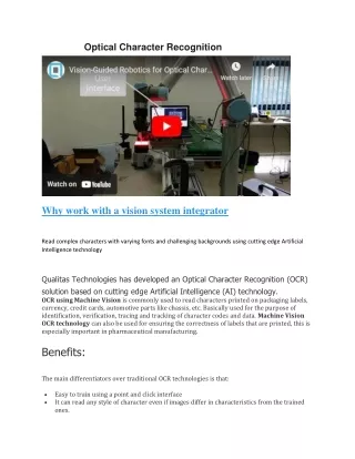
Optical/Laser/Vision Measurement. Unit 94. Objectives. Define both contact measurement and non-contact measurement Describe laser measurement and identify the equipment used for measurement Explain scanning probe technology List the advantages of video-measuring systems.

E N D
Optical/Laser/Vision Measurement Unit 94
Objectives • Define both contact measurement and non-contact measurement • Describe laser measurement and identify the equipment used for measurement • Explain scanning probe technology • List the advantages of video-measuring systems
Measurement: Contact or Noncontact • Contact measurement • Occurs when measuring probe: • Touches workpiece at specified points • Remains in constant contact while recording data points • Uses touch-trigger probe (TTP) method • Used on CMMs for many years • Noncontact measurement means no contact or probing of workpiece
Touch-Trigger Probe Method • Two dimensional (2D) head systems • Axial mode used for profiling • Radial mode used with contour surfaces • Three dimensional (3D) probing head • Used for measuring and inspecting convoluted part surfaces • Where measurements must be made with 3D movements not in machine axes movements
Axial-ScanningMode Z axis is free tomove while theX and Y axes arelocked
Radial-Scanning Mode Z-axis is locked, and the X and Yaxes are free tomove
3D Probe Head Capable of simultaneouslymeasuring inthree axes –X, Y, Z
Optical Comparators • Light passes through condenser lens and projected against workpiece • Shadow transmitted through projecting-lens system which magnifies image and projects it onto a mirror • Image further magnified and reflected to view screen • Image compared with master form • Vernier protractor screen also available
Optical Comparators • Workpiece surface also checked by surface illuminator • Lights up face of workpiece, allowing image to be projected onto screen • Magnification depends on lens used • Interchangeable lenses • 5X, 10X, 31.25X, 50X, 62.5X, 90X, 100X, 125X • Used on small, odd-shaped workpieces
Laser Measurement • Gives ability and flexibility of noncontact measuring • Proving valuable asset • Used in the following: • Manufacturing for welding, machining, heat treatment, measuring, inspection, laser marking, and bar coding
Laser-Tool Measurement • Allows verification of tool integrity, tool wear compensation, and all other aspects of cutting tools • Uses high-precision laser beam and photodiode for measuring operations • CNC machines uses signals generated by system following interruption of laser beam
Laser Scan Micrometer • Highly accurate • Accuracy 62 mm and repeatability of 60.15 mm • Workpiece located in center of laser beam • Creates shadow in path of scanning beam • Enables unit to determine edges of part • Uses uniform high-intensity LED (Light-Emitting Diode) light source and HL-CCD (High-speed Linear Charged-Coupled Device) • Signal digitally processed so high speed sampling at rate of 2400 samples per second
Laser Scan Microscope • Two magnifying lenses • Located specific distance apart • Set distance from eye of observer • Light source used to illuminate sample part • Have accuracy of ½ millionth of an inch
Laser Surface-Finish Measurement • Permits precise, high quality measurement and verification of contours from profile • Hardware based on laser interferometric probe system • Resolution of 5 nm • Up to 150,000 measuring points captured at speeds between 0.02 mm/s and 2 mm/s • Technologies eliminate environmental influences
Scanning Probes • Collect large amounts of data in very short time • Analyze and virtually display data • Noncontact measurement so unaffected by vibration and industrial lighting conditions • Can be used on shop floor where measurements and corrections made while workpiece still in machine
Reverse Engineering • Ability to reproduce parts direction from samples • Parts scanned using scanning CMMs to probe surface or contour of part to be copied • Can provide hundreds of data points allowing for better quality part
Advantages of Video Measuring • Locate randomly oriented parts • Adapt to varying orientations, take measurements and compare them • Used for measuring, inspection, R&D, teaching and documentation • Comfortable for use over long periods since user looking at monitor • Graphical part display provided for measuring sequences
Video Microscope • Starting to replace traditional optical microscopes • Allow image to be magnified onto large monitors or projected • Equipped with video output device which can record and permanently store digital images • Limited by magnification of current video systems
Video Magnifiers • Provides means of electronically enhanced optical-image magnification • Small parts with three-dimensional characteristics • Magnification range between 4X and 50X (or higher) • Black and white or in color
Applications Using Video Magnifiers • In-process inspection • Quality control • Examination of engineering prototypes • ISO training programs
Advantages of Video Magnifiers • Monitor screens provide ergonomic benefits • More than one person can view component • Reduce inspection time
Scanning CMMs • Simple way of automatically collecting large number of data location points • Measure or define shape of object or workpiece • Coordinate measure machine vital to inspection and measurement • Equipped with scanning heads • Digitize and create graphical part representation
Inspection for the Future • Trend toward nano-technology products • Smaller, lighter, and too fragile to measure with conventional mechanical contact • Noncontact scanning will provide ability to perform these operations quickly and accurately with no damage to parts