Download

1 / 19
190 likes | 323 Views
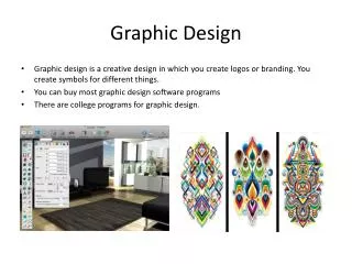
Graphic design Interface. Graphic Design Interface. is the system used to perform drawing and other related graphics operations for the Microsoft Windows family of operating systems. GDI Namespaces. GDI is defined in the Drawing namespace and its five sub namespaces.

E N D
Graphic Design Interface is the system used to perform drawing and other related graphics operations for the Microsoft Windows family of operating systems. GDI Namespaces GDI is defined in the Drawing namespace and its five sub namespaces. All drawing code resides in System.Drawing.DLL assembly. These are System.Drawing, System.Drawing.Printing, System.Drawing.Imaging, System.Drawing.Drawing2D System.Drawing.Text System.Drawing.Design
System. Drawing namespace The System.Drawing namespace provides basic GDI functionality. If contains the definition of basic classes such as Brush, Pen, Graphics, Bitmap, Font etc. The Graphics class plays a major role in GDI and contains methods for drawing to the display device. The following table contains some of the System.Drawing namespace classes, structures and their definition. Classes Description Bitmap, Image Bitmap and image classes. Brush, Brushes Brush classes used define objects to fill GDI objects such as rectangles, ellipses, pies, polygons, and paths. Font, Font Family Defines a particular format for text, including font face, size, and style attributes. Graphics Encapsulates a GDI+ drawing surface. Pen Defines an object used to draw lines and curves. SolidBrush, TextureBrush Defines a brush of a single color. Brushes are used to fill graphics shapes, such as rectangles, ellipses, pies, polygons, and paths
The Graphics Class There're different of ways to get a graphics object in your application. One of these by using the form's paint event as follow Now you've the Graphics object. Now you can do any thing you want. The Graphics class has methods to drawing graphics objects such as fonts, pens, lines, path and polygons, images and ellipse and so on. Some of the graphics class members are described in the following table
The Pen Class A pen draws a line of specified width and style. You always use Pen constructor to create a pen. The constructor initializes a new instance of the Pen class. You can initialize it with a color or brush.
Joins Suppose we have multiple lines that are joined to indicate a shape. The point at which two lines are joined can be rendered with three distinct styles. The Pen class defines how lines are joined. To do so, it provides the LineJoin property. EX:- mypen.LineJoin = Drawing2D.LineJoin.Round
The Point Structure Represents a 2D x- and y-coordinates. Point takes x, y values as a number To Create point object we use the following example EX:- Dim pt1 As New Point(50, 50) Dim pt2 As New Point(300, 50) e.Graphics.DrawLine( Pens.Orange, pt1, pt2) To Create array of points we use the following example of drawing triangle If picture box Size equal to (450,450) EX:- Dim pn as new pen(color.red,8) Dim pnt() As Point = {New Point(225, 25), New Point(425, 425), New Point(25, 425), New Point(225, 25) } pn.LineJoin = Drawing2D.LineJoin.Bevel e.graphics.DrawLines (pn, pnt) 225,25 Drawlines:- draw multiple lines 425,425 25,425
Drawing Basic Shapes • rectangle:- Represents a rectangle with integer values. A rectangle represents two point pair – left, top and width, height. Hint:-size(250,250) , width=200 ,height=100 EX:- Dim g As Graphics = e.Graphics Dim pn As New Pen (Color.Red, 12) pn.LineJoin = Drawing2D.LineJoin.Bevel g.DrawRectangle(pn, 25 , 75, 200, 100) Hint:- the same example can be solve using rectangle instance as: EX:- Dim g As Graphics = e.Graphics Dim pn As New Pen(Color.Red, 12) Dim rect As New Rectangle(25, 75, 200, 100) pn.LineJoin = Drawing2D.LineJoin.Bevel g.DrawRectangle(pn, rect) 25, 75 Drawrectangle:- draw rectangular area 225, 175
2. Ellipse:- An ellipse is simply a circle or oval bound inside a Rectangle structure. To draw an ellipse, you can use the DrawEllipse method of the Graphics class. This method requires a Pen object and some semblance of a rectangle definition Hint:-size(300,300) EX:- Dim g As Graphics = e.Graphics Dim pn1 As New Pen(Color.Red, 5) Dim pn2 As New Pen(Color.DarkBlue, 5) Dim pn3 As New Pen(Color.Yellow, 5) pn3.DashStyle = DashStyle.DashDotDot g.DrawEllipse(pn1, 50, 100, 200, 100) g.DrawEllipse(pn2, 100, 50, 100, 200) g.DrawEllipse(pn3, 50, 50, 200, 200) DrawEllipse:-draw circle or oval shape HW:-رسم الحلقات الاولمبية للعلم الاولمبي الرياضي
3. Polygons:-A polygon is a closed plane, or object, represented by at least three lines (segments). To draw polygons with the namespace, we simply play connect-the-dots. We first create the dots using the Point structure. These dots are actually a series of coordinates through which we will draw lines. To connect the dots, we use the DrawPolygon method of the Graphics class. We indicate the order in which to connect the points of the polygons by their order in our Point array. Draw the following shape with picture box size (400,400) Dim g As Graphics = e.Graphics Dim pn As New Pen(Color.DarkMagenta, 5) Dim mypoint() As Point = {New Point(150, 100), New Point(250, 100), New Point(300, 150), New Point(300, 250), New Point(250,300), New Point(150,300), New Point(100,250), New Point(100,150)} g.DrawPolygon(pn, mypoint) Drawpolygon:-connect dots by lines to draw shape
4. curves:- A curve is an array of points defining the perimeter of a conic section. curves can be used for such things as connecting points on a graph A.Drawcurve method:-Draw curved line passes through an array of points PictureBox1.BackColor = Color.Aquamarine Dim graph As Graphics = e.Graphics Dim pn As New Pen(Color.Blue, 6) Dim mypoint() As Point = {New Point(100, 100), New Point(300, 100), New Point(300, 300)} graph.DrawCurve(pn, mypoint) B.Drawclosedcurve method:-Draw close curve using an array of points. The above example with close curve method. graph.DrawClosedCurve(pn, mypoint)
Filling Shapes:- we've dealt with the outline of a shape. Now we will focus on the interior, or fill area, of a shape. GDI+ gives us the concept of a brush to indicate how a shape is filled. Brushes are useful when blending colors for a desired effect like a fade or indicating a shape's texture like sand, stone, or brick. Brushes can be a single solid color, a blend of colors, a texture, a bitmap, or a hatched pattern. To create brush objects in our code, we use a derivative of theBrush class. Brush is an abstract base class. Classes that derive from Brush are as follows: SolidBrush, TextureBrush, RectangleGradientBrush, LinearGradientBrush, and HatchBrush SolidBrush class :- it provides a single-colored brush with which to fill shapes. It has one constructor and one property, Color. Of course, this property is of the type Color structure. The following is an example of how to create a SolidBrush object Dim myBrush as New SolidBrush (Color.Red) • Dim brsh as new solidBrush(color. BlanchedAlmond) • e.Graphics.FillEllipse(brsh,100, 100, 200, 200) • 2. e.Graphics.FillEllipse(Brushes.BlanchedAlmond,100, 100, 200, 200)
LinearGradientBrush:- In Windows 9x and above, you've undoubtedly seen how you can blend two colors across the title bar of a window from within the "Display Settings" control panel. Well, the LinearGradientBrush class allows us to do just that; we can blend two colors across a given shape.To do so, we first create an instance of the class based on two colors and a blend style. Blend styles are defined by the LinearGradientMode enumeration. We then use a fill method of the Graphics object to paint our shape with the blended style. EX:- Dim rect As New Rectangle (100, 100, 200, 200) Dim brsh As New LinearGradientBrush (rect, Color.Blue, Color.Bisque, LinearGradientMode.Vertical) e.Graphics.FillEllipse(brsh, rect) LinearGradientMode
TextureBrush:- To create custom fill effects, you use the Texture Brush class. Custom fills are useful when you want to apply your own design to the interior of a shape. Using the TextureBrush class and bitmap images, you can create endless fill patterns.The bitmap is defined inside of an ImageList control (imageList1). When we create the texturebrush object, we set the WrapMode parameter to specific mode. Clamp Tile TileFlipX TileFlipXY TileFlipY EX:- Dim rect As New Rectangle(100, 100, 200, 200) Dim brsh As New TextureBrush(ImageList1(). Images.Item(0), WrapMode.TileFlipY) e.Graphics.FillEllipse(brsh, rect)
HatchBrush:- the HatchBrush class allows us to create numerous predefined fill patterns, including brick. We create a HatchBrush by passing in a hatch style, using theHatchStyle enumeration, and a foreground and background color to be used by the hatch style. EX:-Dim rect As New Rectangle(100, 100, 200, 200) Dim brsh As New HatchBrush( HatchStyle.Horizontal, Color.Blue, Color.Yellow) e.Graphics.FillEllipse(brsh, rect) HatchStyle members