Download
1 / 26
260 likes | 390 Views
Gigatracker tasks. presented by A. Kluge CERN/PH-ESE February 2, 2010. GTK system block diagram for one station. GTK station inside vacuum. GTK module. wire bond pads. NA62 trigger. NA62 DAQ. common HV/ LV ground. vacuum feed through. GTK station interface.

E N D
Gigatracker tasks presented by A. Kluge CERN/PH-ESE February 2, 2010
GTK system block diagram for one station GTK stationinside vacuum GTKmodule wire bond pads NA62 trigger NA62 DAQ common HV/ LV ground vacuum feed through GTK station interface humidity &ext. temp sensor GTK read-out electrical/ optical conversion GTK stationout of vacuum GTK service area NA62 trig/DAQ&Read-out 20-40 MultiGigabit optical data fibers 10 optical status fibers 10 x (2.5V+1.2V)+1 HV 10 x (ASIC temp sensor+1 ext. temp+humidity sensor 10 optical configuration fibers GTK cooling plant mechanics control LV power HV power GTK DCS interlock system NA62 DCS GTK service area
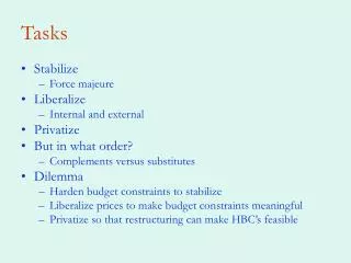
R&D plan Specifications & feasibility studies ASIC & sensor & assembly Electro-mechanical integration & mechanics & cooling Off-detector read-out electronics, interlock, power supply, cabling, DCS software A. Kluge
R&D plan Specifications & feasibility studies ASIC design & prototypes 2 demonstrator ASIC design & production 2 ASIC demonstrator lab evaluation Off-detector read-out electronics, interlock, power supply, cabling, DCS software Electro-mechanical integration & mechanics & cooling 2 ASIC demonstrator bump bonding 2 ASIC demonstrator laser test GTK ASIC architectural choice 2 ASIC demonstrator beam test GTK ASIC design & production A. Kluge
R&D plan Specifications & feasibility studies GTK ASIC design & production GTK ASIC lab evaluation GTK ASIC single chip bump bonding Off-detector read-out electronics, interlock, power supply, cabling, DCS software Electro-mechanical integration & mechanics & cooling GTK single laser (&beam) test GTK ASIC resubmission ? GTK assembly bump bonding GTK assembly laser (&beam) test GTK assembly production A. Kluge
R&D plan Specifications & feasibility studies Cooling prototypes – micro channel & vessel Cooling/vacuum test stand design & constr. Electro-mechanical design & prototype Off-detector read-out electronics, interlock, power supply, cabling, DCS software Electrical/cooling test with single assembly ASIC & sensor & assembly Electrical/cooling test with full assembly A. Kluge
GTK task list A. Kluge
GTK task list A. Kluge
GTK task list A. Kluge
Demonstrator test • ASIC EOC electrical test • ASIC pTDC electrical test • Laser test system construction • ASIC EOC laser test • ASIC pTDC laser test A. Kluge
Test beam preparation • read-out preparation • mechanics preparation • software preparation • test beam • test beam analysis A. Kluge
Demonstrator re-submission • EOC design analysis • EOC layout changes • EOC ASIC submission & production • EOC electrical test • pTDC design analysis • pTDC layout changes • pTDC ASIC submission & production • pTDC electrical test A. Kluge
GTK ASIC design decision A. Kluge
GTK ASIC • GTK ASIC layout design • GTK ASIC submission & engineering run • GTK ASIC carrier card design • GTK ASIC carrier card layout • GTK ASIC carrier card construction • GTK ASIC test read-out card • GTK ASIC electrical test • GTK ASIC laser & source (bump bonding) test • GTK ASIC layout analysis • GTK ASIC layout improvements • GTK ASIC engineering run 2 • GTK ASIC electrical test 2 • GTK ASIC laser test 2 A. Kluge
GTK ASIC production test • GTK ASIC wafer/chip probing station construction • GTK ASIC wafer/chip probing station mechanics design • GTK ASIC wafer probe card design & construction • GTK ASIC wafer probe automatic test procedure • GTK ASIC wafer/chip probing test A. Kluge
Bump bonding & assembly • Dummy bump bonding • Demonstrator bump bonding • GTK ASIC single chip bump bonding • GTK ASIC prototype assembly bump bonding • GTK ASIC assembly bump bonding • GTK assembly test (laser & source) A. Kluge
GTK interface card • GTK interface studies • GTK interface specifications • GTK interface layout design • GTK interface prototype design • GTK interface layout improvement • GTK interface cards final design A. Kluge
GTK mechanics • GTK mechanics design • GTK mechanics construction • GTK mechanics assembly A. Kluge
Module (Mechanics&Cooling&Assembly&Interface card) • Module design • Prototype module construction • Module test – where? • Module construction • Production module test A. Kluge
GTK cooling • vessel cooling studies • vessel cooling prototype • microchannel cooling studies • microchannel cooling prototype • GTK design choice • GTK cooling construction • Power supplies A. Kluge
Interlock • Interlock design • Interlock ordering & installation • Interlock software A. Kluge
GTK Read-out board • Hardware system simulation • Read-out board specification • Read-out board schematic • Read-out board RTL&FPGA simulation • System & board level RTL simulation • Read-out board layout • Read-out board construction • Read-out board test • Read-out board schematic/layout changes • Read-out board final construction A. Kluge
GTK DCS software • ASIC Prototype read-out board DCS • GTK DCS • GTK online data display & consistency check • How it the detector specific DCS integrated in the NA62 environment? A. Kluge
Sensors • Sensor design • Sensor construction • Sensor test A. Kluge
Cables & fibers A. Kluge
Conclusion • Tasks identified • Man power needs to be assigned realistically • Tasks need to be run in parallel A. Kluge