Download
1 / 20
200 likes | 317 Views
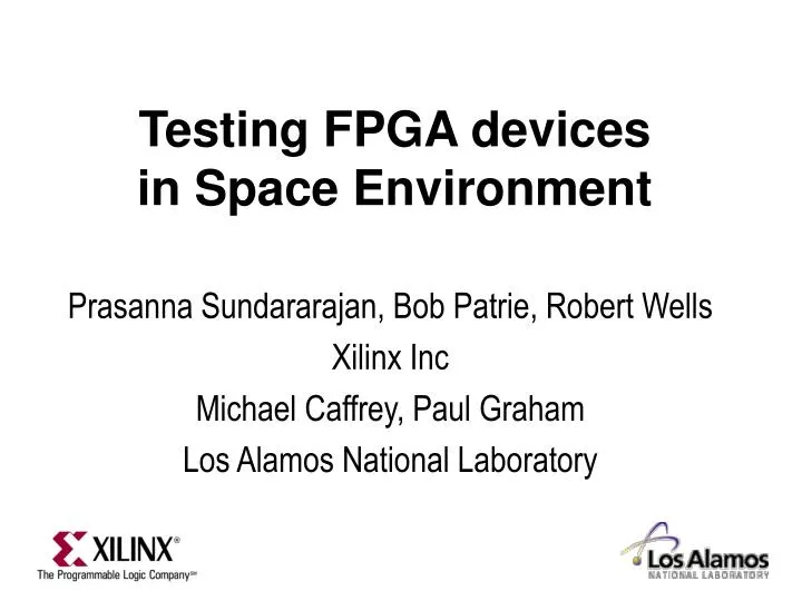
Testing FPGA devices in Space Environment. Prasanna Sundararajan, Bob Patrie, Robert Wells Xilinx Inc Michael Caffrey, Paul Graham Los Alamos National Laboratory. Cibola Flight System. Experimentation platform for FPGA in-situ testing Developed at Los Alamos Laboratory

E N D
Testing FPGA devices in Space Environment Prasanna Sundararajan, Bob Patrie, Robert Wells Xilinx Inc Michael Caffrey, Paul Graham Los Alamos National Laboratory
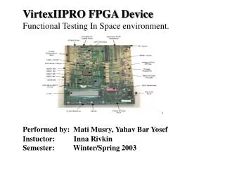
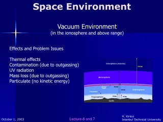
Cibola Flight System • Experimentation platform for FPGA in-situ testing • Developed at Los Alamos Laboratory • LEO orbit RF remote sensing experimental payload • Demonstrates the use of reconfigurable computing on-orbits • Uses 9 XQVR1000 BG560 devices • Used to study system level SEU mitigation perfomances
Cibola Flight System RCC 3 Virtex FPGAs with Memory dcard RCC 3 Virtex FPGAs with Memory dcard RCC 3 Virtex FPGAs with Memory dcard Analog Tuner 2 Channel 12bit ADC@100MHz 2 Channels 20 - 500 MHz RF 2 Channels 55 - 95 MHz IF Results to ground 2 Channel TTL 12 bits@100MHz 2 Channel TTL 32 bits@50MHz • New configurations deployable after launch • Slow ~15 min • Device bitstream readback capability allows: • On orbit readback data analysis (fast < 1 s) • Downloading readback data to earth (fast < 1 min)
RCC Functional Diagram Local SDRAM 3 separate banks each 32 x 8M Processor A FPGA 36 data 3 control Input only: Two 12 bit samples + ECC @50MHz 36 data 3 control Processor B FPGA Local SDRAM 3 separate banks each 32 x 8M 32 data FPDP Buffer 36 data 3 control Input / Output by assembly 32 data Processor C FPGA FPDP Buffer Local SDRAM 3 separate banks each 32 x 8M SEU CRC XQVR configuration Microprocessor interface Actel controller Backplane Interface ASCM
RCC System • Bandwidth • FPDP 200 Mbytes/sec each port (32 bitsx50MHz) • Ring bus up to 104 MHz • Memory 32 bits@52 MHz in 3 independent banks • Each bank 2 parts deep so refresh does not reduce bandwidth, data at every clock • Microprocessor interface ~3 Mbytes/sec • Configuration File Sharing • Bitfiles and designs can be shared amoung any FPGAs as pinouts identical on all XQVR
RCC System Level Test • Built in test will fly • Two test configurations for 9 XQVRs • Tests system from ADC through 3 RCC modules • Tests for open, short, ground bounce and crosstalk • Fault Isolation via verifier ID and failure data pattern • Bitstream SEUs • All XQVR bitstreams readback every 180ms • CRC computed on individual frames and compared with codebook, generated on the ground • Microprocessors can inject SEUs into XQVR1K to observe upset consequence and test system response
RCC System Level Test Verify Test Pattern Generate Test Pattern Local SDRAM 3 separate banks each 32 x 8M 36 data 3 control x3 Local SDRAM 3 separate banks each 32 x 8M 36 data 3 control 32 data FPDP x3 Buffer 36 data 3 control 32 data Local SDRAM 3 separate banks each 32 x 8M FPDP x3 Buffer SEU CRC Processor configuration Actel controller Backplane Interface ASCM Test Pattern 0xFF..FE 0x00..00 0xFF..FD 0x00..00 0xFF..FB 0x00..00 0xFF..F7 System test do not test XQVR Silicon
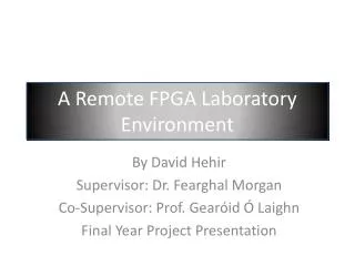
Motivation • SRAM FPGAs offer many features to on-orbit systems: • Processing capacity • Time to market • Cost and Reconfigurability • SRAM FPGAs conducive to in-situ system testing • Lifetime of the SRAM-based FPGA system can be extended • Fault detection and Isolation • Reconfigure around faults
Objectives • Perform In-situ testing of FPGAs on Cibola Flight after depolyment • Enable on-orbit FPGA systems to degrade gracefully • Exploit reconfiguration to extend system lifetime • Understand issues in degradation of systems utilizing SRAM-based FPGAs
In-situ Silicon Testing • Logic testing using Xilinx Reconfigurable Self Test (XRST) • Three bit streams are applied to cover CLB and BRAM: • 100% - LUT RAM & flip flops • 100% - X,Y,XQ,YQ outputs • 100% - F1..F4, G1..G4, BX,BY,CE,SR,CLK inputs • Coverage of additional resources requires additional bitstreams (Carry logic, TBUF, I/O) • BRAM Memory locations • Initial study to conduct wire testing performed
FRCERR Instance 1 Instance 1 GO CONTROL CONFIG INTERFACE Instance N Instance N Drives each Instance CRC XRST Block Diagram CRC
XRST Logic Test • Configure a portion of an FPGA device to perform as a functional tester to: • Apply stimulus • Measure responses • Recorde results • Interchange the portions to be tested with the tester mechanism to provide maximize coverage • Application of the process can be independent of the user system
From previous RAMLFSR From previous MSBCOMP RAMLFSR RAMLFSR RAMLFSR RAMLFSR MSBCOMP MSBCOMP To next MSBCOMP input - XRST Instance Block Diagram From CONTROL FRCERR to 1st RAMLFSR only • A 0 is clocked onto the MSBCOMP chain when the MSBOUT of two or more RAMLFSR’s disagree or when • an error occurs upstream • As CLK edges appear, the 0 is • propagated to the end of the chain • A zeros catcher latches any • 0 transition at the end of the chain • to indicate an error ( some MSBOUT’s differ ) Instance 1 Instance 0 To next MSBCOMP One RAMLFSR output goes to CRC
Test Pattern Floorplans Control RAMLFSR Other BLK RAM #1 #2 #3 Cover Even Rows Cover Odd Rows Cover Control Area + Block RAM Control Area not tested - 28 CLB’s
In-situ Wire Testing • Complete wire testing requires more patterns than the logic testing • Initial study was conducted to estimate the number of configurations required to test “Singles” wire type • It was assumed that the configurations to test the wire would be uploaded from the ground station
Wire Testing • Testing Singles wire type • Total 96 singles/CLB with 24 in each direction • 20 of 24 singles have OMUX associated with them • Initial tests cover 80 single wires/CLB • 4 singles/CLB can be tested in parallel in one single session • One Test Session => One configuration, 2 readback • Total of 20 configuration and 40 readback would be needed
4 LUT Buffer/ Inverter 4 LUT Buffer/ Inverter Wire Test O M U X FF Singles Wire Under Test
Wire Test Session • Configure the test data • Column 0 as buffer and other columns as inverters • Connect the CLB with the wire under test • Init all FF to ZERO • Step Clock 1 • Send Readback Command • Readback entire CLB data and check for SA-1 • Step Clock 1 • Send Readback Command • Readback entire CLB data and check for SA-0 • Iterate above steps to test other singles
Compression of Test Patterns • To reduce the time required to transport the data, test patterns were compressed • GZIP compression utility from Java development kit was used
Summary & Future Work • FPGAs are uniquely suited for in-situ testing after deployment • A novel self-test mechanism to test the logic resources was developed • Initial study to test the wire types was conducted • Graceful system degradation possible by fault detection and isolation • Future work would involve design specific routing testing to maximize coverage