Download

1 / 14
140 likes | 225 Views
ROMAN POT ( POSSIBLE NEW DESIGN) PRESENTED by G. SPIGO on behalf of ROMAN POT Mechanical Team (E. Richards and G. Spigo).

E N D
ROMAN POT (POSSIBLE NEW DESIGN) PRESENTED by G. SPIGO on behalf of ROMAN POT Mechanical Team (E. Richards and G. Spigo)
In the figure above it is shown a possible solution to avoid the interference with the so-called QRL (Cryogenic Distribution Line) of the LHC machine. In fact, in the current design, there is clear conflict between the QRL and the bottom bellow of the Roman Pot.
In this cross section view it is shown the basic idea to solve the problem. In the current design, the flange in the red circle is connected to the tube displayed in the yellow circles. The idea is to lift the bottom bellow above the flange so as to eliminate the conflict with the QRL. In order to do so, it is proposed to make the connection between the flange and the two bellow by means of an intermediate piece, which has a cylindrical shape.
The proposed way to manufacture the assembly in order to be vacuum proof is the following: The tube previously connected to the flange is cut. The two pieces, always attached to the bellows are welded to a flat plate (orange circle) 3) The bellow-tube –plate assemblies are welded to a cylinder where a pipe union is extruded
Welding between tube and plate Welding between plate and cylinder Extrusion in the cylinder
To prevent and avoid any possible buckling of the bellows due to push-pull forces acting on them, it is proposed to fix two calibrated rods (red lines) in the middle plates of the assembly. To make friction forces negligible, these rods will slide inside recirculation ball bearings or once-for-all lubricated bronze bearings that are mounted in the top or in the bottom piece (yellow circles) of the assembly.
CALCULATIONS With respect to the picture shown in the previous transparency, it has been considered that two rods having a diameter of 16 mm could be fixed to one of the two plates of the “buffer” making the connections between the two bellows. Tentatively, the rods will have a diameter of 16 mm (the be bought from any length varying from 300 to 2500 mm) and will glide in Slide Bushes inserted in the top and bottom pieces connected to the bellows. The Slide Bushes will have a length of 36 mm and an external diameter of 26 mm. So, by doing so, any possible out-of-plane stress will be compensated and the “bucking” of the bellow prevented. The material chosen for the buffer will be the austenitic steel alloys grades AISI 304L or 316L, since the piece is welded. Different diameters and thicknesses can be chosen for the buffer tube to be welded to the top and bottom flanges. In our case, tentatively the diameter of the buffer tube will be between 165 and 195 mm and the wall thickness between 3 and 4 mm.
Let us calculate the wave length of the tube in order to understand if the edge effects can be important. • = 2*p/a =2*p*(R*t)1/2/[3*(1-n2)]1/4 = > 76 < l < 95 (mm) • As the height of the buffer tube will be around 80 – 90 mm to permit the welding of the small tube that allows the vacuum connection, one can say that in any case the edge effects on the buffer tube will be reduced by at least a factor of: • e-ax = e–al/2 = e–p = 0.043214, which means that the edge effects are 23 times less. • Let us consider that the flanges welded to the buffer tubes are infinitely rigid in order to calculate the maximum possible stress. This means that the diameter deformation will be less than the real one (difference around 2%). • w = C*e-ax sin(ax + y) • M = 2*a2*B*C*e-ax sin(ax + y -2p/4) where B = E*t3/[12*(1-n2)] • Therefore for x = 0 => w = 0 and w’ = 0 • Then: y = p/4 and C = - 1.4142*p*R2/(E*t)
The values of w and M are the following: w = p*R2*[1- 1.4142*e-axsin(ax + p/4)]/(E*t) M = - (1.4142*p*R*t/3.4)*e-axsin(ax - p/4) Therefore, for x = 0: M = 0.294*p*R*t (8.16 Nmm/mm) and for l/2, w = 1.043*p*R2/(E*t) s1max = M*6/t2 = 0.294*p*R*6/t = 1.764*p*R/t = 5.41 MPa s2max = w/(R*E) = 1.043*p*R/t = 3.2 MPa sid= √(s1max2 + s2max2 - s1max * s2max) = 4.71 MPa < sadm= 172.7 MPa So, the stress in the buffer tube is quite low The maximum deformation is: w = 1.043*p*R2/(E*t) = 0.00151 mm -------------------------------------------------------- The top and the bottom flanges of the buffer can be modeled as annular plates fixed at their edges (t = 3 mm as starting point).
The values of srmax and sqmaxare the following: srmax = 0.75* p*R2/t2 = 70.5 MPa sqmax= -n*srmax= - 23.5 MPa sid= √(srmax2 + sqmax2 - srmax *sqmax) = 84.7 MPa < sadm= 172.7 MPa So, the stress in the flanges welded to the tube is well below the admissible stress. The maximum deformation (fixed edges) is: w = 3*(1-n2)*p*R4/(16*E*t3) = 0.23 mm The maximum deformation (simply supported) is: w = 3*(5+n)*(1-n)*p*R4/(16*E*t3) = 0.95 mm To limit the deformation, the correct value for flanges should be around 10 mm. sid= 7.6 MPa w (fixed edges) = 0.06 mm w (simply supported) = 0.026 mm
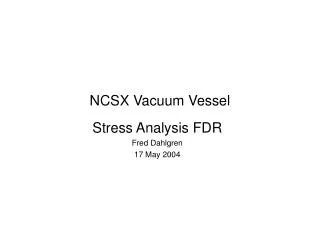
To countercheck the values of bending moments found above and have a better idea of the validity of the assumptions as in reality the flange is neither simply supported nor with fixed edges. So, it has been considered the following scheme: Hc In the figure above, it shown a reservoir submitted to an external pressure. The mutual bending moment Mc can be calculated by equalizing the different rotations. In order to do so, one has to compute the mutual coefficients of the tube. These are the following: Mc l D = 2R
wh = (2*a/b)* [(sinhal*coshal – sinal*cosal)/(sinh2al-sin2al)] fh = (2*a2/b)* [(sinh2al +sin2al)/(sinh2al-sin2al)] fm = (4*a3/b)* [(sinhal*coshal + sinal*cosal)/(sinh2al-sin2al)] w’h = (2*a/b)* [(cosal*sinhal – sinal*coshal)/(sinh2al-sin2al)] f‘h = (4*a2/b)* [(sinal*sinhal)/(sinh2al-sin2al)] f‘m = (4*a3/b)* [(cosal*sinhal + sinal*coshal)/(sinh2al-sin2al)] The system of equations is: pR2/(Es) - wh* Hc - w’h* Hc + fh * Mc - f‘h * Mc = 0 fh* Hc - f‘h * Hc - fm * Mc + f‘m * Mc = - p*R3/[8*(1+n)*B] + Mc*R/[*(1+n)*B] where: a = [3*(1-n2)]¼/√(R*s), b = E*s/R2, B = E*t3/[12*(1-n2)], s = 3 mm and t = 10 mm By solving the equations one obtains: Mc = 29.8 Nmm/mm and Hc= 3.0 N/mm
The maximum stress provoked by Mc is: • 1’ = 6*Mc/s2 = 19.87 MPa in the tube • In the tube one has to add s2= p*R/(2*s) = 1.53 MPa and s1 = P*R/s = 3.06 MPa • In the top and bottom flanges: • 1’ = 6*Mc/t2 = 1.79 MPa • In the flange one has to add s2 = Hc/t = 0.3 MPa and • s1tot = 3*(3+n)*p*R2/(8*t2) - s1’ = 8.68 MPa • As in the tube there is the hole to connect the vacuum, the increase of stress in the area surrounding the tube can be evaluated with the theory of stress concentration factors and it resulted to be between 4 and 5 times. • So, let us take the worst value. The new figure of s2 close to the hole is around 5*1.53 = 7.65 MPa • Then, it can be concluded that the level of stress in this assembly is safe and its designing can go ahead to be finalized in order to find the best manufacturing choices for its fabrication.