Download
1 / 29
290 likes | 351 Views
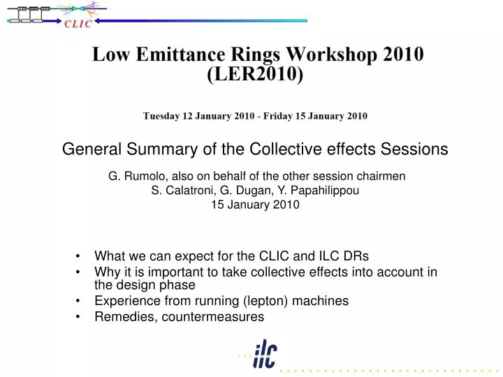
General Summary of the Collective effects Sessions G. Rumolo , also on behalf of the other session chairmen S. Calatroni , G. Dugan , Y. Papahilippou 15 January 2010. What we can expect for the CLIC and ILC DRs

E N D
General Summary of theCollectiveeffectsSessionsG. Rumolo, also on behalf of theothersessionchairmenS. Calatroni, G. Dugan, Y. Papahilippou15 January 2010 • Whatwecanexpectforthe CLIC and ILC DRs • Whyitisimportant to takecollectiveeffectsintoaccount in thedesignphase • Experiencefromrunning (lepton) machines • Remedies, countermeasures
From the LER workshop program • 4 sessions were entirely devoted to collective effects over Wednesday and Thursday • Ion effects and IBS • Electron cloud • Simulations, measurements • Mitigation techniques • Impedance related issues • 3 WebX talks during Wednesday’s sessions could not take place due to technical problems with the WebX connection • 2 talks on the ATF experience on FBII and IBS • 1 overview talk on electron cloud issues for both ILC and CLIC damping rings (M. Pivi)
From the LER workshop program (II) • Overview talks • Ion effects, impedance in lepton machines • Chamber coatings • Experimental results from running machines and lab measurements • CSR at Anka • Electron cloud studies at Cesr-TA and KEKB • Electron cloud instabilities at DAFNE • Use of NEG coating at Soleil • Impedance studies and reduction at DAFNE, ELETTRA • Scrubbing as a function of electron energy • Studies for future facilities (using simulation codes) • Electron cloud in SUPERKEK and SUPERB • IBS and Touschek for PEP-X • Vacuum design for ILC-DR • Results of novel methods of calculation • IBS with self-consistent beam distributions • Taper impedances • Resistive wall impedance with coating and in the THz regime
Why are collective effects so important for the CLIC and ILC Damping Rings ILC-DR CLIC-DR • High number of bunches • High intensity per bunch • Close bunch spacing and short bunches • Low transverse emittances, low gaps From S. Guiducci Bunch spacing 6 ns
Courant faisceau Pression vide Two-stream phenomenaIon effects in electron rings • Due to residual gas ionization ions can be generated and then trapped around a bunch train • Even if the presence of a gap between trains clears the ions, a Fast Beam Ion Instability (ex. SOLEIL below) can be excited over one train • The threshold for this instability critically depends on the pressure in vacuum chamber (and residual gas composition) From R. Nagaoka
Two-stream phenomenaIon effects in electron rings • Usually the FBII has been observed in electron rings • During commissioning/start up (chamber not yet conditioned, bad vacuum) • Because of some localized pressure rise (e.g., directly connected to heating caused by impedance degradation) • Artificially induced by injecting gas into the chamber and raising the pressure by more than one order of magnitude • It seems to be stabilized by other effects (yet to be explained) • No quantitative comparison between theoretical predictions and measurements From R. Nagaoka Dual sweep streak camera image of a bunch train (M. Kwon et al., Phys. Rev. E57 (1998) 6016)
Two-stream phenomenaIon effects in positron rings • Ions from gas ionization can also cause trouble in the positron DRs • When lost to the chamber walls, they produce more molecules according to their energy and the wall desorption yield • Consequently, more ions are produced and the process can lead to an ion induced pressure instability From O. Malyshev
Two-stream phenomenaSuppression of the ion effects • Very good vacuum required • In the electron DR, to be sure that we are far enough from the FBII threshold • In the positron DR, to be sure that there is no pressure instability • NEG coating seems a good option • Other types of coatings (provided they are UHV compatible) could be envisioned for the positron DR (against electron cloud, see next slides) • SOLEIL experience shows the advantages of activated NEG coating • Lower photon stimulated desorption • No vacuum limitation at the beginning, fast recovery after venting + re-activation • But ALS has uncoated Al chambers and seems to have equally good performances… From C. Herbeaux
Two-stream phenomenaElectron cloud • In the positron DR, electron cloud formation is an issue • Primary electrons (seed) come from: • Photoemission from synchrotron radiation (can be significant even without multiplication) • Gas ionization (negligible) • Multiplication to be avoided by keeping the Secondary Emission Yield below 1. ILC CLIC From M. Pivi & T. Demma Simulations show that both for the CLIC and ILC DRs SEY<1.2 is necessary, as well 99% absorption of the SR
Two-stream phenomenaElectron cloud simulations • Electron cloud simulations are based on codes for • Build up (ECLOUD, POSINST, CLOUDLAND,..) • Single bunch instability (HEADTAIL, PEHTS, WARP, CMAD,…) • Coupled bunch instability (PEI-M) • Based on tune shift measurement, code predictions have been benchmarked against experimental data at Cesr-TA (simulation parameters tuned) From G. Dugan
Two-stream phenomenaElectron cloud simulations • Coupled bunch instability data from DAFNE (only positron ring) have been compared with the simulations with PEI-M • Very good agreement found, which confirms that the observed instability is caused by electron cloud Horizontal instability on mode -1 From T. Demma
Two-stream phenomenaElectron cloud mitigation/suppression techniques • To combat electron cloud: • Surface coating with low SEY materials (Cu, NEG, TiN, a-C) • Non-smooth surfaces (natural roughness, grooves) • Clearing electrodes • Solenoids • Conditioning, scrubbing From S. Suetsugu From T. Demma
Two-stream phenomenaSurface coating (I) • Experience with coatings at KEK shows that: • Aluminum needs to be coated! • TiN coating is better than NEG coating • However, TiN coating shows large desorption at the beginning (improves with scrubbing) From S. Suetsugu
Two-stream phenomenaSurface coating (II) • Experience with coatings at CERN shows that: • Stainless Steel has maximum SEY>2 • a-C coating is slightly better than NEG coating (from direct electron signals) • Pressure data on a-C coated vs. uncoated chambers not fully understood yet • In any case, a-C does not need activation/baking and the experience at the SPS over 1.5 years shows that it is stable and very robust against ageing. From M. Taborelli
Two-stream phenomenaSurface coating (III) • Experience with coatings at Cesr-TA shows that: • a-C is well behaved also with respect to photoemission (at least factor 10) • a-C coating is slightly better than TiN coating, at least with positrons • RGA shows peaks for CO and CO2 at the gauge close to the a-C coated chamber From M. Taborelli
Two-stream phenomenaClearing electrodes • Experience with clearing electrodes shows that: • There is a drastic reduction of the electron cloud when the voltage is applied • Beware of the impedance! • Low impedance design needed From S. Suetsugu
Two-stream phenomenaGrooved surface • Experience with a grooved surface at KEK shows that: • Also grooves are effective against cloud formation • No significant change with beam dose, however it produces less electrons than all the other surfaces • Impedance does not seem to be an issue (GdfidL simulations) From S. Suetsugu
Two-stream phenomenaConditioning, scrubbing • Many machines rely on scrubbing to reduce the SEY of the pipe walls and increase the current threshold for electron cloud build up • The scrubbing “e-folding dose” depends on the energy of the impinging electrons • The final SEY value also depends on the energy of the electrons, low energy electrons (which dominate the energy spectrum in an e-cloud) are not equally efficient From R. Cimino
ImpedancesClearing electrodes: impedance issue • Clearing electrodes at DAFNE (originally installed in the electron ring, to clear from ions) shows that: • They can significantly contribute to the impedance • Bunch lengthening, quadrupole instability, vertical emittance blow up (they all disappeared after removing the electrodes) • New low impedance design being implemented for the electron clearing electrodes to be installed in the positron ring From M. Zobov
ImpedancesResistive wall impedance: high frequency & coating • The resistive wall phenomena in the DRs need to be studied taking into account that: • The frequency regime to be covered is much higher, which also entails a few unknowns (a.c. conductivity, anomalous skin effect…) • The influence of coatings for vacuum or electron cloud suppression • Solution found for axisymmetric structure with multi-layer boundary • Impedance and wake field (needed for beam dynamics simulations with HEADTAIL) Bunch length Bunch to bunch Bunch train . . . From N. Mounet
ImpedancesInfluence of coating on the ring impedance • At ELETTRA an increase of the slope of the tune shift with intensity was observed after the installation of NEG chambers • More measurements done at ESRF and Soleil showed that NEG coating should have increased the machine impedance by a smaller amount From E. Karantsoulis
ImpedancesGeometric contributions from tapered transitions • There is a low frequency regime in which the impedance from tapers is purely inductive • Impedance can be minimized by shaping the taper • Both calculations and EM simulations with ECHO and ABCI confirm the impedance reduction (within a small factor for the elliptical and rectangular cases) • In the optical regime (probably important for the short bunches of the damping rings) the taper behaves like a step transition From B. Podobedov
ImpedancesGeneral • The accelerator design must be oriented to impedance minimization • Smooth design based on tapering without abrupt transitions (broad-band impedance, especially important for single bunch stability) ILC vacuum vessels design Tapering to chamber with antechamber Tapering to the wiggler chamber From O. Malyshev
ImpedancesGeneral • The accelerator design must be oriented to impedance minimization • While designing a future facility, the contributions to the impedance can be evaluated based on existing machines • All contributions summed up and compared with the impedance budget From K. Bane
ImpedancesGeneral • The accelerator design must be oriented to impedance minimization • HOM as well as potentially harmful trapped modes have to be damped (narrow-band resonators, especially important for coupled bunch stability) From M. Zobov
Instabilities & beam quality degradationGeneral • Many types of instabilities have been observed in the existing machines, and often limit their performance • Coupled bunch instabilities (e.g., e-cloud in DAFNE, FBII in SOLEIL) • Transverse Mode Coupling Instability (ELETTRA) • Head-tail instabilities on mode 0, or higher (ELETTRA, SOLEIL) • Bunch lengthening, hitting sometimes the microwave instability threshold (DAFNE, ELETTRA) • Emittance blow up (DAFNE, SOLEIL) • Low emittance design enhances the sensitivity to most of the mechanisms underlying these phenomena (R. Nagaoka) • Small momentum compaction means short bunch and high synchrotron tune • Transversely small bunches • Instabilities are usually suppressed with: • High positive chromaticity, but this excites higher order head-tail modes and could deteriorate the beam lifetime • Landau cavities for bunch lengthening (perhaps the DRs could have longer bunches and compress them before extraction?) • Impedance reduction (beam based measurements to spot impedance sources and remove) • Active feedback system (multi-bunch or single-bunch, see Instrumentation summary)
Instabilities & beam quality degradationGeneral • High brilliance is also associated to more space charge and IBS, which are potentially responsible for beam quality degradation, or could prevent a DR from reaching the design emittance • Space charge included in the nonlinear tracking for the CLIC DRs, it causes the formation of tails, which can be very much populated for working points close to resonance lines (discussed in the session of Nonlinear Dynamics) • IBS calculations • modeled taking into account a self-consistent particle distributionfor the CLIC DRs. While the vertical emittancelevels off to a value very close to nominal, the horizontal emittance is almost twice the nominal value. • Bjorken-Mtingwa (BM) method with a fast algorithm, applied to PEP-X calculations • Both effects depend on the optics and need to be considered in the lattice design From K. Bane From A. Vivoli
Instabilities & beam quality degradationCoherent Synchrotron Radiation • Unshielded CSR from main and fringe fields is an important effect for machines operating with short bunches (mainly in the THz regime) • CSR can cause a microwave-like instability • Saturation of this instability and radiation damping leads to a sawtooth-like patterna as a function of time • CSR changes with bunch current and shape From A. Müller
Conclusions • Most of the collective effects play equally important roles in the design of both the ILC and the CLIC DRs, as well as of future high energy lepton machines • Electron cloud (DRs, SUPERKEKB, SUPERB), ions • IBS (DRs, PEP-X), space charge • Impedance driven instabilities enhanced by the low emittance design • Efforts to find solutions and suppression techniques are conducted in synergy between different communities • Lab measurements (coatings, scrubbing efficiency) • Learn from experience of running machines (vacuum, methods for instability suppression, impedance reduction campaign based on beam measurements), understand impedance degradation, which can lead to heating, pressure rise and ion instabilities • New tests in the existing machines, benchmark of e-cloud simulation codes (Cesr-TA) • Design of accelerator components optimized for the beam impedance (nonlinear tapers, strip-line kickers, low impedance clearing electrodes, …) • Better understanding of resistive wall in the THz frequency regime and of coated walls • Big thanks to all the speakers and those who contributed to the discussion