Download
1 / 17
220 likes | 543 Views
Non-contact Ultrasonic Pulse Velocity Method for Concrete. Gonzalo P. Cetrangolo University of Illinois at Urbana-Champaign. CEE 498 Prof. Daniel Kuchma. March, 2006. Outline. Introduction Stress wave propagation and Methods for Structure Maximize Energy transfer

E N D
Non-contact Ultrasonic Pulse Velocity Method for Concrete Gonzalo P. Cetrangolo University of Illinois at Urbana-Champaign CEE 498 Prof. Daniel Kuchma March, 2006
Outline • Introduction Stress wave propagation and Methods for Structure • Maximize Energy transfer Quarter wavelength matching layer • Experimental results through air • Experimental results through concrete • Conclusions
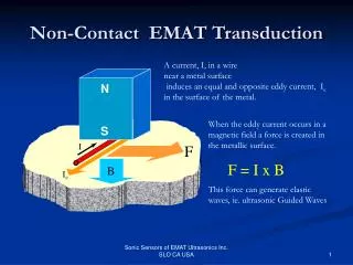
Stress-Wave propagation in solid half-space elastic media Stress waves occur when pressure or deformation is applied suddenly (such as by an impact source) P-wave: longitudinal waves propagate parallel to the propagation direction: VL= [E(1-n)/(r(1+n)(1-2n))] E:Young’s Modulus r: Mass density n: Poisson’s ratio S-wave: shear waves propagate perpendicular to the propagation direction: Vs= [G/r] G:Shear Modulus r: Mass density R-wave: surface waves propagation only near surface (half space): VR/Vs=(0.87+1.12n)/(1+n) n: Poisson’s ratio
Stress-Wave Methods for structures • Ultrasound through thickness Time of flight • Ultrasound echo-method Time of flight • Spectral Analysis of Surface Waves Dispersion curves • Impact Echo method Resonance frequency
Ultrasonic Methods Pulse Velocity Method Pulse echo Method Direct Configuration Indirect Configuration ACI document 228-1R Arrival time of a stress wave reflected from a defect (difference in Acoustic Impedance) is determined ACI document 228-1R The timer shows the time of flight of the direct through thickness P-wave arrival VL = Travel path / time of fight In both cases, transducers are coupled to the surface using a viscous material such as grease.
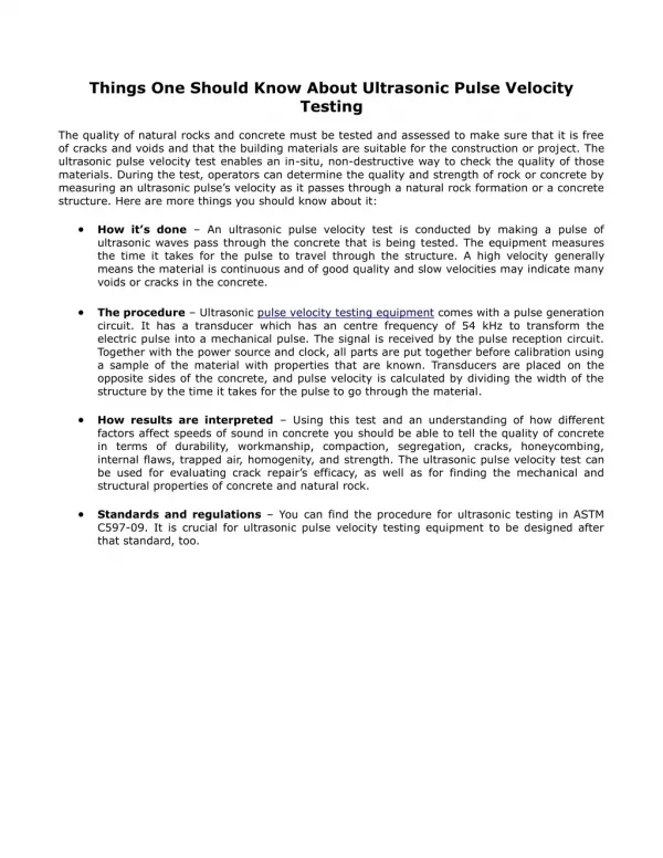
Ultrasonic Pulse Velocity • UPV has been used to asses the quality of the concrete successfully for several years • Identify areas of concrete damage • Locate defects and voids • Locate delaminations • Estimate in place-strength by using calibration curve • Coupling agent is needed between transducers and specimen
Benefits of Air coupled • Coupling agent between the transducers and concrete surface are time and labor intensive • Results variability caused by difference in the pressure use to keep the transducer clamp to the surface • Allow to test concrete having rough surface • Allow faster inspection
Product information • The Ultran Group is the only producer of Non-contact transducers for through thickness measurements • The only technical information available of these transducers is in their own webpage • The cost of the equipment is U$S 20,000, which include a field computer, transducers set and a pulser unit.
Air-Concrete reflection/transmission Normal incidence Material 1 Material 2 Z2-Z1 Z1+Z2 Ai At R= Ar = Ai Ar 2*Z2 Z1+Z2 T=1+R = Air-Concrete interface R: ratio of sound pressure of the reflected wave to the sound pressure of the incident wave Zair= 0.4 kg/(m2s) T: ratio of sound pressure of the transmitted wave to the sound pressure of the incident wave Zconcrete = 9*106 kg/(m2s) Ai: Amplitude of the incident wave Ar: Amplitude of the reflected wave R=0.9999999 Ar: Amplitude of the transmitted wave T=0.0000001 Z1: specific Acoustic Impedance of material 1 Z2: specific Acoustic Impedance of material 2
Maximize wave energy transfer Quarterwavelength Matching layer Wave energy transfer between two distinct media is maximized when an appropriate intermediate impedance matching layer is inserted. Matching Layer Air Waves in phase Vibrating Crystal Select and attach the optimal impedance matching layer between the vibrating piezoelectric crystal in the UPV transducer (PZT-4) and air
Experimental Setup Matching layer caps Sender Receiver Air Gap Oscilloscope LeCroy LT344 Pulser unit • A pair of 24 kHz modified transducers with matching layer caps • Pulser unit (UPV Pulser from James Instruments) • Oscilloscope LeCroy LT344
Experimental Results through air Modified transducer set with matching layer Time domain signal through air Amplitude Amplitude(Volts) FFT 19.5 kHz Time(ms) Frequency (Hz) Unmodified contact transducer set Time domain signal through air Amplitude Amplitude(Volts) FFT 19.5 kHz Time(ms) Frequency (Hz)
Experimental Results through air • Signals through different air gaps Modified transducer set • The original transducers provide a narrow-band ultrasonic pulse at a center frequency of 19.5 kHz. • The transducer has a 38 mm diameter face, giving a near-field distance in air of 16 mm. • Maximum received Amplitude at 9mm distance between transducers face. • Local maximum every 9mm. Amplitude(FFT) Air gap distance (mm) Unmodified transducer set Amplitude(FFT) Air gap distance (mm)
Behavior at 9 mm air gap? Air gap resonance matches transducer crystal resonance V air= 344 m/s f PZTcrystal= 19.5kHz V air= 2 * D air gap* fPZT-4 crystal D air gap = V air / (2* fPZT-4 crystal) D air gap= 9 mm Resonance at 9 mm, 18 mm, 27 mm, 36 mm, … D = n * l/2 n = 1, 2, 3 … Impedance matching layers provide 300% increase in received signal amplitude through air.
Measurement through concrete Signal through air Experimental setup (air) 7.2 cm of air gap Foam Foam Signal through concrete Experimental setup (concrete) 9mm air gap Foam Foam 5.4 cm of concrete V concrete= d concrete / (time concrete - time air+d concrete / V air)
Conclusions • Impedance matching layers provide 300% increase in received signal amplitude through air • Impedance matching layers and 9 mm air gap between the modified transducers and the sample enable contact-less through-thickness P-wave Velocity measurements in concrete specimens up to 10 cm thick showing similar behavior as standard full contact UPV • Averaging of the received signal increase the SNR
References [1] ACI Committee 228 (2003). “In-place methods to estimate concrete strength (ACI 228.1R-03)”. American Concrete Institute, Farmington Hills, Mich. [2] Berriman, J., Purnell, P., Hutchins, D.A. and Neild, A. (2005).“Humidity and Aggregate Content Correction Factors for Air-coupled Ultrasonic Evaluation of Concrete” Ultrasonics 43 (4) (211-217). [3] Gomez Alvarez-Arenas, Tomas E. (2004). “Acoustic Impedance Matching of Piezoelectric Transducers to the Air”, IEEE Transactions on Ultrasonics, Ferroelectrics, And Frequency Control 51 (5) (624-633) . [4] Krautkramer, J. and Krautkramer, H. (1990). Ultrasonic Testing of Materials, fourth ed., New York, Springer-Verlag. [5] Lide, David R., ed.(1998-1999). CRC Handbook of Chemistry and Physics, 79th ed., Cleveland, Ohio.