Download
1 / 20
200 likes | 260 Views
Microcavity Multipixel Performance Report 4. HV Card and Dead T ime Pixel Uniformity Run with 3 Rows of Pixels Hardware challenges Comments. C. F erretti , D. Levin. Quick Recap of Single Pixel Results. Microcavity (MC1) filled with AAT0001 at 737 Torr

E N D
MicrocavityMultipixel Performance Report 4 HV Card and Dead Time Pixel Uniformity Run with 3 Rows of Pixels Hardware challenges Comments C. Ferretti, D. Levin University of Michigan PPS
Quick Recap of Single Pixel Results • Microcavity (MC1) filled with AAT0001 at 737 Torr • Quench: 100 MΩ HV card + 1GΩ pixel • Waveform similar for all the pixels: |A|~1V, FWHM~2ns, Rise Time~2ns • Three main results: 64h single pixel <rate>10’ Rate stable over days Six single pixel rate vs HV Plateau similar for all pixels collimated 106Ru ~4-6 Hz Single pixel (R5-3) arrival time σ≈5 ns (at 1150V) University of Michigan PPS
Pixel Quench 1GΩ 100 MΩ ~150 μs dead time with 100MΩ ~1.3 ms dead time with 1GΩ X-axis 500 μs/div Y-axis 200 mV/div X-axis 500 μs/div Y-axis 500 mV/div • RC=200 M𝝮 x 0.25 pF dead time=3 *RC= 3*50 μs= 150 μs • With 100MΩ at 1050V the single pixel 106Ru rate is doubled respect to 1GΩ dead time not long enough back to the 1G𝝮, but this time on the HV card • Dead time is expected to be again~1.3 ms. Instead it was still below 200 μs • Added an extra 1G𝝮 in line with the HV, but this too had no effect on dead time! • The HV card itself is a capacitor (~2.6 nF, two ground planes) replenishing the little pixel capacitance (fraction of a pF), while recharging with a characteristic time much longer new HV card and back to 1GΩ at the pixel University of Michigan PPS
Line 10 Recovery The RO cable for line 10 (and the ground line nearby) was disconnected re-attached just soldering and worked and then got detached again University of Michigan PPS
Line 1 Recovery RO line 1 disconnected because of a damaged pad due to sparks between it and the nearby ground line re-attached with conductive epoxy (John) University of Michigan PPS
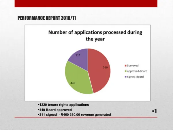
Pixel by Pixel Test Each pixel tested at 1050V as the only one in HV-RO crossing “Current” result: 51/63 OK (81 %) 2/63 Dead (3 %) 3/63 Noisy (5 %) 7/63 Sparking (11%) University of Michigan PPS
Single Pixel Background Rate Included one not-too-noisy pixel University of Michigan PPS
Single Pixel Collimated 106Ru–bkg Rate No systematic error included forthe source positioning University of Michigan PPS
Multi-Pixel Tests Instrumented the first 3 lines (HV #3, 5, 7 and partially 10) without any dead or sparking pixel (and RO line #10). Total 23/29 pixels. University of Michigan PPS
Multi-Pixel Background 2 3 2 3 2 2 3 3 3 0 Number of active pixel/line University of Michigan PPS
106Ru 15 cm Above the Panel The illumination was more or less uniform. The rate (at 1050 V) on each line is proportional to the number of active pixels on that line! Pixel rate(~ 0.3 Hz) more thanone order ofmagnitudeabove background(~0.015 Hz) 3 pixels line 2 pixels line University of Michigan PPS
Going for The Full Test University of Michigan PPS
1 GΩ on All Good Pixels • 1st time: one pixel sparked at ~970 V. The solder flowed across the bottom of the resistor and shorted it outfixed • 2nd time: another pixel sparked at ~1000 V. While not shorted out, the resistor had solder flows creating a current path fixed • 3rd time: around 1030 V, visible glowing of a dozen of the new resistors discharges at a very high rate, suggesting that nearly all the newly installed resistors were providing an effectively very small resistance dismounted all of them and adding only a few new resistors at the time following the HV lines • 4th time: readout line (#5) completely dead. Cable disconnected from the pad as for line 10? It turned out that both 50Ω on the RO card were fried (~26MΩ and 4.6MΩ) by one sparking pixel. Once replaced the line was OK University of Michigan PPS
Lesson Learned • The accepted technique of microdrop of Kester solder-in-flux deposited on the resistor pads is inappropriate as the tiny Pb-Ag balls can float around and underneath the component creating an archipelago of solder balls that can bridge the 1 GΩ (differently from PCB missing raised separator between the pads). • The preferred method, so far, is to pre-tin the resistors and the pads, clean off the residue then solder the resistors into place • One pixel showing high noise was recoveredby dismounting, cleaning and re-soldering the pixel quench resistor. Likely it is possible to recover at least a few more sparking • We will try to use the digital soldering iron (at 850°F) and the special solder 96.5% Sn / 3.0% Ag / 0.5% Cu used for the cables University of Michigan PPS
More Pixel, Igor! Added a fourth row of pixels (HV #13) and things start to change - Background rate remains OK - Rate collimated source on pixel ~ OK - Noise on other lines is higher and higher as we get far away from RO University of Michigan PPS
One More HV Row Background and pixel close to RO still OK But not the position of the collimated source is barely recognizable University of Michigan PPS
Correlated Pulses on Scope X=50 ns Y=500 mV RO Line2, Line 3, Line 4 The problem increases far from RO: with HV#18 on. Itis not even possible to reach 1050V, background rates ~100Hz at 1020V! Possible explanations University of Michigan PPS
Why? Possible ways that cells communicate • Photon propagation • However, the cavities are metalized and embedded. • There is no obvious path for photons to move from one cavity to another. • The observed delay time of 100 ns is much too long for photons. • Ion-propagation. While the gas channels do not directly connect one pixel to another, there could be a significant gas gap between the top layer and bottom substrate: Exaggerated view if top plate is not flush with bottom substrate
Positive ions or charged CF4 can migrate through the gap to a nearby pixel + - + - - + + + + + + + +
Conclusions • Collimated source over the nearest neighbor or 5 pixels away in both cases gives ~ 2 x background collimator works well • Current HV board prevents splitting quench resistors between pixel and HV line (only pixel count) new one without ground planes near HV already designed • Hardware very sensitive: adding new pixels is very tricky and takes quite a bit of practice and time, RO line can loose connection and the repair is difficult, … (Resistive paste in the via seems risky) • The initial single spark often seen on newly connected pixel suggests the possible presence of dust next prototype better if assembled in a clean room • Important to image the cavities before the assembly in order to match eventual imperfections with faulty/noisy/uncharacteristic pixels • Suspect of not perfect parallel assembly of the two substrates (possibly due to uneven epoxy, not parallel planes, distortions, …) • Results of pixels test results both in single and in combinations • pixel background rate much lower than the one whit (collimated) source • the rate of a line can be predicted by the number of pixels instrumented they are really working as isolated entities University of Michigan PPS