Download
1 / 4
40 likes | 156 Views
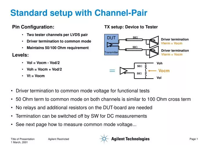
DUT Transmitter. 50 Ω. Driver termination Vterm = Vocm. 50 Ω. Driver termination Vterm = Vocm. Voh. 50 Ω. Vocm. 50 Ω. Vol. Standard setup with Channel-Pair. TX setup: Device to Tester. Pin Configuration: Two tester channels per LVDS pair Driver termination to common mode

E N D
DUT Transmitter 50Ω Driver termination Vterm = Vocm 50Ω Driver termination Vterm = Vocm Voh 50Ω Vocm 50Ω Vol Standard setup with Channel-Pair TX setup: Device to Tester Pin Configuration: • Two tester channels per LVDS pair • Driver termination to common mode • Maintains 50/100 Ohm requirement Levels: • Vol = Vocm - Vod/2 • Voh = Vocm + Vod/2 • Vt = Vocm • Driver termination to common mode voltage for functional tests • 50 Ohm term to common mode on both channels is similar to 100 Ohm cross term • No relays and additional resistors on the DUT-board are needed • Termination can be switched off by SW for DC measurements • See next page how to measure common mode voltage... Agilent Restricted
‘Classic’ way for DC common mode measurement • Run a preconditioning pattern to bring the device outputs to a defined state • Measure the output voltages for ‘one’ and ‘zero’ on both lines of the pair • Calculate and check the common mode voltage for both cases • Can be implemented with testflow variables, as a userprocedure or a testmethod Preconditioning Measurement Preconditioning Measurement Calculation & Check VOp_0 VOn_1 VOCM_0 VOCM_1 PASS/FAIL VOn_0 VOp_1 GND • VOCM_0 = Vop_0 - Von_0 • VOCM_1 = Von_1 - Vop_1 Agilent Restricted
Solution proposal #1: Relays to switch-in resistors Tester Channel 50 • Switch in the resistors only when they are required • Run high-speed functional test with standard driver termination to Vcom • Minimize Reflections on the ‘open’ line by keeping the connection path very short Device Driver 50 Tester Channel 10 K 50 50 pF 50 Tester Channel 50 Loadboard Agilent Restricted
Solution proposal #2: Relays to switch-in resistors Tester Channel 50 • Switch in the resistors only when they are required • Run high-speed functional with standard driver termination to Vcom • No ‘open ends’ in the relays for functional measurement Device Driver 50 Tester Channel 10 K 50 50 pF 50 Tester Channel 50 Loadboard Agilent Restricted