Download
1 / 55
700 likes | 1.5k Views
Routing Algorithms. Dynamic Routing. The routing table is updated using the routing protocols . When there is a change in the Internet such as router breakdown or link failure, the routing protocols update all the information in the routing tables.

E N D
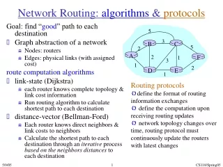
Dynamic Routing • The routing table is updated using the routing protocols. When there is a change in the Internet such as router breakdown or link failure, the routing protocols update all the information in the routing tables. • For the dynamic routing, routers should exchange routing information using routing protocols. • routing information • information about network topology, delay, etc. • routing protocol • It specifies the routing messages and procedures to exchange the routing information to determine routes. Network Layer
Internet Routing Architecture • Internet architecture from routing’s views • It is unrealistic to apply a single routing protocol to the worldwide Internet because of its size. • So, the worldwide Internet is divided into many groups, which are administered independently. • These independent groups of networks are called the autonomous systems(AS) which are assigned 16 bits long AS number. • AS • “a group of networks and routers controlled by a single administrative authority” • Each AS needs to inform its routing information of other ASs. For this purpose each AS has more than one border routers. Network Layer
Autonomous System 1 Autonomous System 2 Subnet 1.2 Subnet 2.1 R3 R2 R6 Subnet 1.1 Subnet 1.3 Subnet 2.2 R5 R7 R1 R8 Subnet 2.4 R4 Subnet 1.4 Subnet 2.3 LEGEND: Interior Gateway Protocol Exterior Gateway Protocol Network Layer
Internet Routing Protocols • Interior Gateway Protocol (IGP) • IGP is operated within each AS. • Each AS can operate its own IGP. • Most well-known IGPs • RIP(Routing Information Protocol) • OSPF(Open Shortest Path Find) • Exterior Gateway Protocol (EGP) • To exchange packets between AS, the AS border routers should exchange the routing information. • EGP is the routing protocol between ASs. • BGP(Border Gateway Protocol) Network Layer
IGPs Network Layer
Distance Vector Algorithm • (assume that the metric is delay) • Step 1: Each router exchange ECHO packet to measure the time • to reach each neighboring routers. • Step 2: Each router send this information to its neighboring routers • periodically. • The information contains the times to reach all other routers. • Step 3: Each router determines the mim. time to reach all other routers • using step 1 and 2. And update its own routing table. Network Layer
Echo 패킷 m sec (TAB, TAC, TAD, TAE) Example B C A J Ti sec D TB = m + TAB TC = m + TAC TD = m + TAD TE = m + TAE E Network Layer
Example: sample network D C B A H G E F L K J I Network Layer
new information from A, I, H, K Network Layer
New information on the neighboring nodes • Suppose that the delay from J to A, I,H, and K 8,10,12,6 secs respectively. • Then what is the next hop router and the delay to reach G from J? J ---> A -------> G 8 + 18 = 26 J ----> I -------> G 10 + 31 = 41 J ----> H ------> G 12 + 6 = 18 (best route for JG) J ----> K ------> G 6 + 31 = 37 Network Layer
Updated routing table of J Network Layer
Link state Routing • Overview • Each node collects the topology information of the whole network, and then computes the shortest paths to reach each node using the Dijkstra algorithm. • The routing protocols such as ISO’s IS-IS and IETF’s OSPF belong to this algorithm, and they will replace the DVA routing protocol. • Examples • OSPF for TCP/IP • ISO’s IS-IS for CLNS and IP • DEC’s DNA Phase V • Novell’s NLSP(Netware Link services protocol) Network Layer
Link state Routing Algorithm • Discover the neighboring node. (send Hello message periodically) • Measure the link costs to the neighboring nodes. • Make the Link State packet. • Broadcast the Link State packet to all nodes. • After receiving the Link State packets from all other nodes, make the link state database. • Compute the shortest paths to reach all other nodes based on the link state database. Network Layer
Step1: Collect the link state information from the neighboring nodes and make the link state packets. D seq# age A 2 B 2 C 3 E 1 E seq# age C 1 D 1 F 1 A seq# age B 2 C 5 D 2 B seq# age A 2 C 3 D 2 C seq# age A 5 B 3 D 3 E 1 F 1 F seq# age C 1 E 1 Example of Link state routing 5 B C 1 3 F 3 2 2 1 3 A 2 1 D E Link state packets Network Layer
Example of Link state routing Step 2: Propagate the link state information to all other nodes. • Make the link state packet. • Use the flooding. Step 3: Compute the shortest path. • Based on the link state information, the node makes the link state database that represents the whole network topology. • Compute the shortest path using the Dijkstra algorithm. Network Layer
Link # Cost Link # Cost Link # Cost A-B A-C A-D B-A B-C B-D C-A 2 5 2 2 3 2 5 C-B C-D C-E C-F D-A D-B D-C 3 3 1 1 2 2 3 D-E E-C E-D E-F E-C E-E 1 1 1 1 1 1 Link State Database 5 B C 1 3 F 3 2 2 1 3 A 2 1 D E Network Layer
Internet Routing Protocols Network Layer
Intra-AS Routing • Also known as Interior Gateway Protocols (IGP) • Most common Intra-AS routing protocols: • RIP: Routing Information Protocol • OSPF: Open Shortest Path First • IGRP: Interior Gateway Routing Protocol (Cisco proprietary) Network Layer
RIP • IETF standard routing protocol • Based on the Distant Vector algorithm • The hop count is used as the metric. • The hop count is 1 for an adjacent network. • The hop count 16 means infinity.(network is not connected.) • Each router exchange routing information every 30 secs. • The routing information contains the whole routing table entries. • Each advertisement: list of up to 25 destination nets within AS • It uses the UDP port number 520. • It was first implemented in the UNIX 4.2 BSD. Network Layer
Procedure Receive a response RIP message 1. Add one hop to the hop count for each advertised destination 2. Repeat the following steps for each advertised destination: If (destination not in the routing table) Add the advertised information to the table else if (next-hop field is the same) replace entry in the table with the advertised one else if (advertised hop count smaller than one in the table add it to the routing table else do nothing 3. Return Network Layer
RIP: Example(1) Network Layer
RIP: Example(2) Network Layer
RIP: Example(2) Network Layer
RIP message reserved version Command family All 0s Network address 반복 All 0s All 0s distance Command : request (1) or response (2) The unsolicited response is transmitted periodically every 30 secs. Family: TCP/IP (2) distance : hop count Network Layer
Problems of DVA(RIP) • Problems • scalability • Slow convergence • In particular, when the shortest paths are changing rapidly, the inconsistency between routing tables can happen, since the updated routing information propagates slowly. • count-to-infinity problem • Not proper to be expanded to multicast routing protocol. Network Layer
Net D R 1 1 R1 Net D R 1 - Net D R 1 - Good news go travels quickly! Net 1 up R1 R2 R3 distance next router • good news go fast! • When the connection with the network 1 is added, the routing table can reach the stability after 2 message exchanges. destination Initial state (N1,1) Net D R 1 1 R1 Net D R 1 2 R1 Net D R 1 - time (N1,1) (N1,2) (N1,2) Net D R 1 1 R1 Net D R 1 2 R1 Net D R 1 3 R2 Note: (x, y) = (destination network, Distance) Network Layer
Net D R 1 - Net D R 1 2 1 Net D R 1 3 2 Count-to-infinity Problem(1) crash Net 1 R1 R2 R3 Initial state (N1,2) (N1, ) (N1,3) (N1,2) Net D R 1 3 2 Net D R 1 4 3 Net D R 1 3 2 (N1,4) (N1,3) (N1,3) (N1,4) Net D R 1 5 2 Net D R 1 4 3 Net D R 1 5 2 time (N1,4) (N1,5) (N1,5) (N1,4) Net D R 1 5 2 Net D R 1 6 1 Net D R 1 5 2 . . . . . . . . . Net D R 1 - Net D R 1 - Net D R 1 - Network Layer
Count-to-infinity Problem(2) • Bad news goes slowly!! • In the previous picture, when the connection between R1 and network 1 is broken, the cost (distance) to network 1 grows to infinity gradually. • When the cost reaches to 16, the router knows that the connection is broken. • When the bad news occur, it takes a long time to be aware of that.(slow convergence) • Solutions • Split Horizon • Hold down • Poison reverse Network Layer
Solutions to the Count-to-infinity Problem • Split horizon update (withPoison Reverse) • The router interface that receives the information about a certain network should send information about that network to other routers as infinity (distance=16) • It cannot be applied to all kinds of topologies. • Route poisoning • If a router receives the information that the hop count to a certain network increases, it sets the hop count=16, and send it to other routers, suspecting a loop might occur. Network Layer
Split Horizon • A router should never send the routing update information to the interface through which it received the corresponding routing information. routing message routing message Net1 2 Net2 1 Net2 1 Net3 2 Net1 1 Net3 1 Net1 Net3 Net2 A B Network Layer
Poison reverse • When a router sends the routing update message to all routers, it says to the interface from which it received the information about the network that the cost to the network is infinity (cost=16). routing message routing message Net1 1 Net2 16 Net3 16 Net1 16 Net2 1 Net3 2 Net1 2 Net2 1 Net3 16 Net1 16 Net2 16 Net3 1 Net1 Net3 Net2 A B Network Layer
RIP: Link Failure and Recovery If no advertisement heard after 180 sec --> neighbor/link declared dead • routes via neighbor invalidated • new advertisements sent to neighbors • neighbors in turn send out new advertisements (if tables changed) • link failure info quickly propagates to entire net • poison reverse used to prevent ping-pong loops (infinite distance = 16 hops) Network Layer
routed routed RIP Table processing • RIP routing tables managed by application-level process called route-d (daemon) • advertisements sent in UDP packets, periodically repeated Transprt (UDP) Transprt (UDP) network forwarding (IP) table network (IP) forwarding table link link physical physical Network Layer
OSPF (Open Shortest Path First) • “open”: publicly available • Uses Link State algorithm • LS packet dissemination • Topology map at each node • Route computation using Dijkstra’s algorithm • OSPF advertisement carries one entry per neighbor router • Advertisements disseminated to entire AS (via flooding) • Carried in OSPF messages directly over IP (rather than TCP or UDP Network Layer
OSPF “advanced” features (not in RIP) • Security: all OSPF messages authenticated (to prevent malicious intrusion) • Multiple same-cost paths allowed (only one path in RIP) • For each link, multiple cost metrics for different TOS (e.g., satellite link cost set “low” for best effort; high for real time) • Integrated uni- and multicast support: • Multicast OSPF (MOSPF) uses same topology data base as OSPF • Hierarchical OSPF in large domains. Network Layer
Hierarchical OSPF Network Layer
Hierarchical OSPF • Two-level hierarchy: local area, backbone. • Link-state advertisements only in area • each nodes has detailed area topology; only know direction (shortest path) to nets in other areas. • Area border routers:“summarize” distances to nets in own area, advertise to other Area Border routers. • Backbone routers: run OSPF routing limited to backbone. • Boundary routers: connect to other AS’s. Network Layer
Internet inter-AS routing: BGP • BGP (Border Gateway Protocol):the de facto standard • BGP provides each AS a means to: • Obtain subnet reachability information from neighboring ASs. • Propagate the reachability information to all routers internal to the AS. • Determine “good” routes to subnets based on reachability information and policy. • Allows a subnet to advertise its existence to rest of the Internet: “I am here” Network Layer
Anonymous System(AS) Autonomous System 1 Autonomous System 2 Subnet 1.2 Subnet 2.1 R3 R2 R6 Subnet 1.1 Subnet 1.3 Subnet 2.2 R5 R7 R1 R8 Subnet 2.4 R4 Subnet 1.4 Subnet 2.3 LEGEND: Interior gateway protocol Exterior gateway protocol Network Layer
Autonomous System (AS) • AS • “ a set of routers under a single technical administration, using an Interior Gateway Protocol and common metrics to route packets within the AS and using an Exterior Gateway Protocol to route packets to other ASs” (RFC 1771) • Today AS may use more than one IGP, with potentially several sets of metrics. • The autonomous system designator is a 16-bit number, with a range of 1 to 65535. A range of AS numbers, 64512 through 65530, is reserved for private use, much like the private IP addresses. Network Layer
Path attributes & BGP routes • When advertising a prefix, advert includes BGP attributes. • prefix + attributes = “route” • Two important attributes: • AS-PATH: contains the ASs through which the advert for the prefix passed: AS 67 AS 17 • NEXT-HOP: Indicates the specific internal-AS router to next-hop AS. (There may be multiple links from current AS to next-hop-AS.) • When gateway router receives route advert, uses import policy to accept/decline. Network Layer
BGP messages • BGP messages exchanged using TCP. • BGP messages: • OPEN: opens TCP connection to peer and authenticates sender • UPDATE: advertises new path (or withdraws old) • KEEPALIVE keeps connection alive in absence of UPDATES; also ACKs OPEN request • NOTIFICATION: reports errors in previous msg; also used to close connection Network Layer
BGP Example AS 1 N1 AS 2 N2 R1 1 N3 R2 1 R51 AS 3 AS 5 R3 R52 R4 AS 4 Network Layer
BGP Example • R1 • Obtain the network information in AS1 by exchanging the IGP routing messages between routers in AS1. • R1 sends BGP UPDATE message to all BGP neighbors. • The UPDATE message includes: • AS_Path: {AS1} • Next_Hop: {R1’s IP address} • NLRI: {N1, N2, N3} • R2, R3 • R2 and R3 that received the UPDATE message can know that the networks in AS1 can be reached via R1. Network Layer
BGP Example AS 1 N1 AS 2 N2 R1 N3 R2 2 R51 AS 3 AS 5 R3 2 R52 R4 AS 4 Network Layer
BGP Example • R2 sends to R51 the UPDATE message that includes the following: • AS_Path: {AS1, AS2} • Next_Hop : {R2’s IP address} • NLRI: {N1, N2, N3} • R3 sends to R4 the UPDATE message that includes the following: • AS_Path: {AS1, AS3} • Next_Hop : {R3’s IP address} • NLRI: {N1, N2, N3} Network Layer
BGP Example AS 1 N1 AS 2 N2 R1 N3 R2 R51 AS 3 AS 5 R3 3 R52 R4 AS 4 Network Layer
BGP Example • R4 sends to R52 the UPDATE message that includes the following: • AS_Path: {AS1, AS3, AS4} • Next_Hop : {R3’s IP address} • NLRI: {N1, N2, N3} Network Layer
BGP Example AS 1 N1 AS 2 N2 R1 N3 R2 R51 AS 3 AS 5 R3 R52 R4 AS 4 Network Layer