Download
1 / 47
470 likes | 549 Views
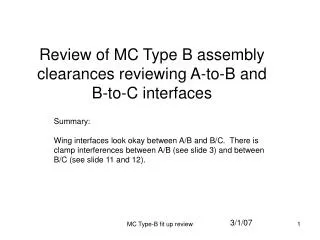
Review of MC Type C to C assembly clearances with C2 to C5 shell surface interface details. 12/19/06. Rev 4. 1. 10. C2. 20. 30. C5. Sec - C. Sec – D looking outside. 50. 40. C2. 30. C5. Sec - B. Sec - A. Sec – D looking inside. Clamp interference.

E N D
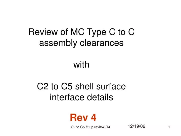
Review of MC Type C to C assembly clearanceswithC2 to C5 shell surface interface details 12/19/06 Rev 4 C2 to C5 fit up review-R4
1 10 C2 20 30 C5 Sec - C
50 40 C2 30 C5 Sec - B
0.25 offset of inner surface of poloidal break leaves 0.073” clearance
0.25 offset of inner surface of poloidal break leaves 0.073” clearance Based on final C2 measurements, MC C2 poloidal break extends inward 0.19” along the full surface. See slide 24.
Type C2 0.323” min clearance to Interfacing Type C
MTM metrology data points shown as white points. Steve’s original metrology data points are red points Interfacing Type-C wings is shown in overlay with underside surface represented.
0.264 0.28 0.67 0.222 0.247 0.575 0.363 0.267 0.294 0.33 0.253 Type C2 0.634 Interfacing Type C wing 0.448 0.481 Slide taken from review: C2 MTM metrology review-R1 0.566 There are minimum points to inspect but Se141-116-wing-c clearance looks okay with a 0.222” clearance identified at one location. The underside surface of the wing is typical out by +0.025”, leaving a minimum clearance of 0.197”.
Interfacing Type C wing Type C2 0.221” min clearance
Additional grinding on Type C2 was done in region shown. Mark up for 1/6” -1/8” grind area Slide taken from review: C2 MTM metrology review-R1
Slide taken from review: MC C5 review-R1 The surface offset of pints in the blue area is in the range of +.075” to .102”. Nominal surface cut is .12” Are we deep enough? The surface offset of pints in the pink area is in the range of +.021” to +.039” except where noted. Offset of pints in the orange area is in the range of .020” to .037”. +.038 +.036 +.032 +.038 +.037 +.043 +.041 +.042 +.039 +.048 +.054 C to C Side Outside Large Wing E Side +.050 +.055 +.054 +.070 +.052 +.067 The values shown is the machined surface of the large Wing C male side. It will interface with the surface shown in slide 6.
The following slides are full wing and flange scans of C2 and C5 Mike Ducdo data: 120606_c2_wing_scan.IGS. Points shown are centers of 1.5” Ø measurement probe.
120606_c2_wing_scan DATA The as-built surface is generally off by +0.030” with a few front edge point out be +0.050”
120606_c2_wing_scan DATA General 0.35” C to C CAD space in this area 0.03” to 0.05” 0.19” MTM 0.20” Duco 1.18” to C5 0.03” to 0.04” 0.058” MTM 0.061” Duco 0.065” MTM 0.070” Duco 0.23” min C to C CAD space
120606_c2_wing_scan DATA 0.23” min C to C CAD space. surface measured data is in the range of 0.0” to +0.01”
+0.06” Out of Tolerance in the enclosed area. +0.10” OOT at the root (point indicated) +0.02” to -.08” surface variation over the remainder of the cut region. MC C2 metrology data shown
MC C2 metrology data shown MC C2 poloidal break extends inward 0.19” along the full surface.
The C5 small wing geometry is similar to C2 (see slide 30). Based on final measurements of C2 and C5 a gap of +0.033 exists at the poloidal break interface area. Local grinding on this wing is needed to increase the gap.
121106_c5_wing_scan DATA The as-built surface is generally off in the range of +0.030” to +0.050”
121106_c5_wing_scan DATA General 0.35” C to C CAD space in this area 0.05” 0.02” to 0.06” 0.20” Duco 1.18” to C2 0.170” Duco 0.87” to C2 0.050” Duco 0.42” to C2 0.23” min C to C CAD space
121106_c5_wing_scan DATA 0.23” min C to C CAD space. surface measured data is in the range of -0.05”
+0.06” Out of Tolerance in the enclosed area. +0.16” OOT at the root (point indicated) +0.05” to -.02” surface variation over the remainder of the cut region. MC C5 metrology data shown
MC C5 metrology data shown MC C5 poloidal break extends inward 0.18” along the full surface. I though C5 break inner surface was nearly flush… check this.
MC C2 metrology data MC C5 metrology data Surface -0.02” to +0.14” Surface measures -0.07” to -0.13” Surface -0.05” to +0.15” Surface measures -0.13” to -0.17”
Measured CAD distance with C2 and C5 located in their translated positions. The movement of C2 and C5 was made using Art’s large motion case (r1) provided in email (FW C1-4 Realignment Coordinate Transformations in ProE nomenclature) dated 10/6/06. C2 was positioned using C2r1 data and C5 positioned using C4r1 data. The translated position is based on the CS0 coordinate system. Origin (inches) Orientation (degrees) X Y Z About X About Y About Z C1r1 0.00040934 0.00674867 0.00309482 0.00402910 -0.00164692 -0.00234224 C2r1 -0.00323208 -0.03096037 0.02236041 0.02613692 0.05253439 0.01904024 C3r1 -0.01426276 -0.01285752 -0.02457020 0.03075978 0.03998892 -0.01316786 C4r1 0.01163284 0.00620140 0.01452996 -0.03328320 -0.00150808 0.00988164
C5 0.1997” CAD gap C2
C5 0.311” CAD gap C2 Large wing underside local surface
0.336” CAD gap C5 Large wing local front nose surface C2
C5 0.461” min bladder inner surface CAD gap C2 Inside surface of bladder pocket
C2 0.212” CAD gap C5
C2 0.375” CAD gap C5
C2 0.371” CAD gap Large wing local front nose surface C5
Side-B 0.4297” CAD gap 0.443” CAD gap C5 Side-A C2 0.567” CAD gap (inside corners) Side-A 0.560” CAD gap
C5 4.35” +.06” AB 0.58” at root 0.311” CAD clearance to underside surface of poloidal break. Expected gap = .311 -.20 - .06 = +.051” +.2” AB break lower surface C2
C5 0.387” CAD clearance to underside surface of poloidal break. Expected gap = .387 -.20 - .06 = +.127” 4.2” C2 0.62” at root
Post grinding C5 +0.039” blue -0.042” red Plane located 4.35” from flange face. -0.025” red +0.043” blue -0.047” red -0.00” red
● ● ● • 8 monuments are located on each mating MC, so positioned that they can be seen by the Lica metrology system which has been optimally positioned. The monuments are to be located on stable surfaces where part deflection is minimal. • The first MC is positioned on the Stage 2 support stand and secured in place. • A reference coordinate system (to be designated ACS0) will be determined through metrology measurement of the first MC, referencing the 8 monuments.
C2 pt 2 C2 pt 1 C2 pt 3 C5 corner pts


![Intro: [ C5,C]x2,[G,G7]x2,C,C5,C,G C G C Need a location, eh?](https://cdn2.slideserve.com/3993368/slide1-dt.jpg)