Download
1 / 5
50 likes | 57 Views
"The robust LED display has been designed using 9 mm high characters (the largest possible) and with a slight incline in order to make reading the pressure as easy as possible from a long way off. A 14-segment display has been used, since it represents text very well.<br>The 3-key operation makes simple, intuitive menu navigation possible, with no need for additional assistance. The menu navigation conforms to the latest VDMA standard. The VDMA standard for fluid sensors (24574-1, part 1 - pressure switches) has the aim of simplifying the use of electronic pressure switches by standardising menu navigation and display."<br>For More Information visit on:- www.seeautomation.com<br>Our Mail I.D:- sales@seeautomation.com<br>Contact Us:- 91-11-22012324 , 8144883403<br>

E N D
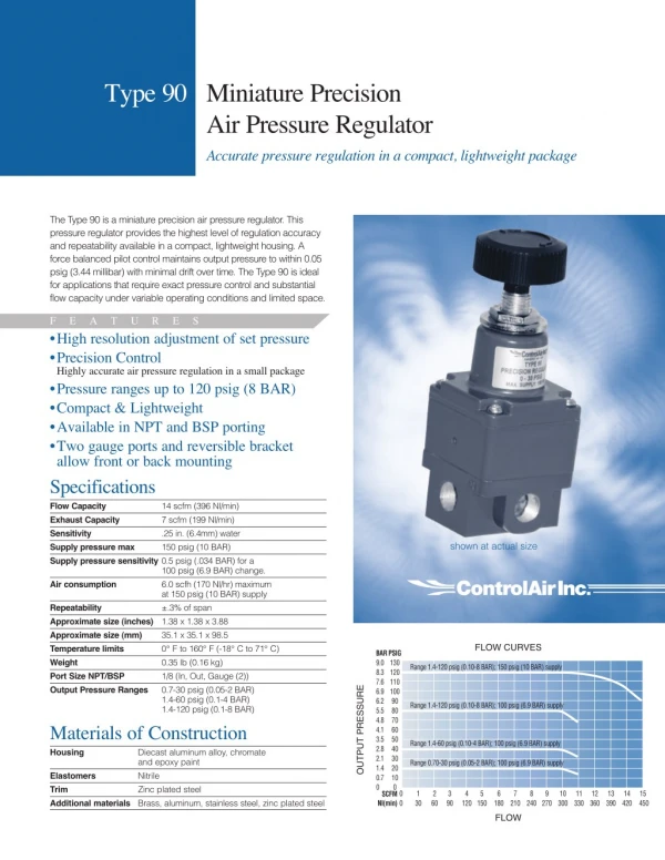
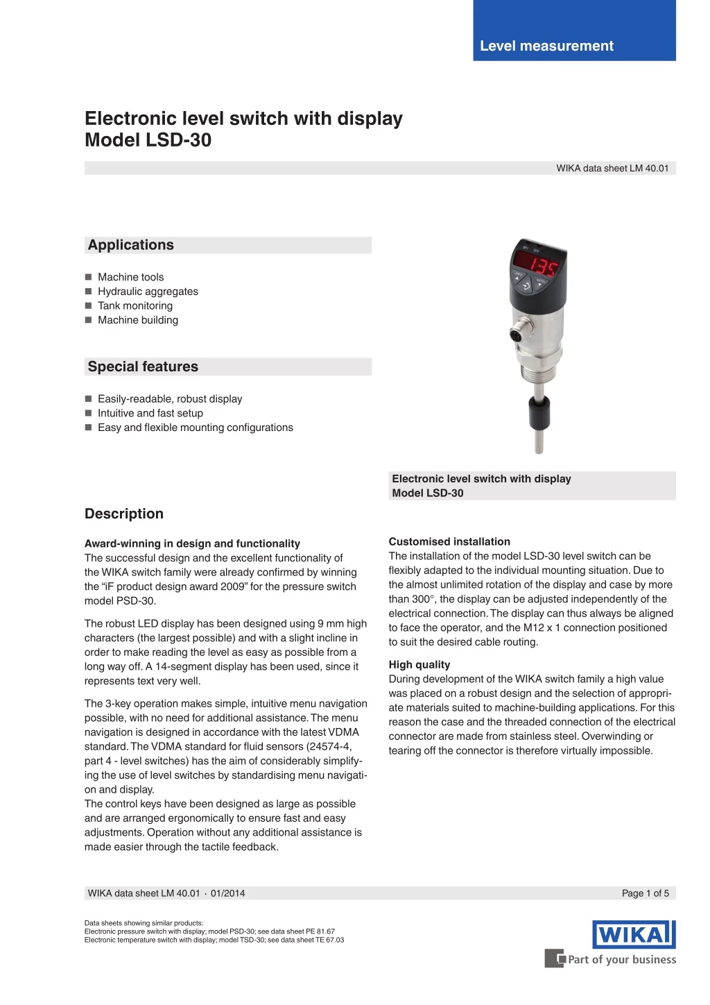
Level measurement Electronic level switch with display Model LSD-30 WIKA data sheet LM 40.01 Applications ■ Machine tools ■ Hydraulic aggregates ■ Tank monitoring ■ Machine building Special features ■ Easily-readable, robust display ■ Intuitive and fast setup ■ Easy and flexible mounting configurations Electronic level switch with display Model LSD-30 Description Customised installation The installation of the model LSD-30 level switch can be flexibly adapted to the individual mounting situation. Due to the almost unlimited rotation of the display and case by more than 300°, the display can be adjusted independently of the electrical connection. The display can thus always be aligned to face the operator, and the M12 x 1 connection positioned to suit the desired cable routing. Award-winning in design and functionality The successful design and the excellent functionality of the WIKA switch family were already confirmed by winning the “iF product design award 2009” for the pressure switch model PSD-30. The robust LED display has been designed using 9 mm high characters (the largest possible) and with a slight incline in order to make reading the level as easy as possible from a long way off. A 14-segment display has been used, since it represents text very well. High quality During development of the WIKA switch family a high value was placed on a robust design and the selection of appropri- ate materials suited to machine-building applications. For this reason the case and the threaded connection of the electrical connector are made from stainless steel. Overwinding or tearing off the connector is therefore virtually impossible. The 3-key operation makes simple, intuitive menu navigation possible, with no need for additional assistance. The menu navigation is designed in accordance with the latest VDMA standard. The VDMA standard for fluid sensors (24574-4, part 4 - level switches) has the aim of considerably simplify- ing the use of level switches by standardising menu navigati- on and display. The control keys have been designed as large as possible and are arranged ergonomically to ensure fast and easy adjustments. Operation without any additional assistance is made easier through the tactile feedback. WIKA data sheet LM 40.01 ∙ 01/2014 Page 1 of 5 Data sheets showing similar products: Electronic pressure switch with display; model PSD-30; see data sheet PE 81.67 Electronic temperature switch with display; model TSD-30; see data sheet TE 67.03
Measuring ranges Display 14-segment LED, red, 4-digit, character size 9 mm Display can be turned electronically through 180° for process connection G ¾ A Sensor length F (mm) Measuring range (mm) 189 Measuring range (inch) 7.44 250 370 309 12.17 410 349 13.74 520 459 18.07 730 669 26.34 Update 200 ms for process connection ¾ NPT Sensor length F (mm) Measuring range (mm) 205 Measuring range (inch) 8.07 250 370 325 12.80 410 365 14.37 520 475 18.70 730 684 26.93 Voltage supply Power supply U+ DC 15 ... 35 V Insertion lengths see “Dimensions in mm” Specific gravity range of the medium ≥ 0.7 g/cm3 Current consumption Switching outputs with ■ Analogue signal 4 ... 20 mA: ■ Analogue signal DC 0 ... 10 V: 45 mA ■ without analogue signal: 70 mA Output signal 45 mA Switching output SP1 PNP PNP PNP PNP PNP Analogue signal Total current consumption max. 600 mA (incl. switching current) SP2 - - PNP PNP PNP 4 ... 20 mA (3-wire) DC 0 ... 10 V (3-wire) - 4 ... 20 mA (3-wire) DC 0 ... 10 V (3-wire) Measuring element Resistance measuring chain with reed switches and float Optionally also available with an NPN instead of a PNP switching output. Resolution < 6 mm Switching thresholds Switch point 1 and 2 are both individually adjustable Response time < 700 ms Maximum operating pressure 3 bar Switching functions Normally open, normally closed, window, hysteresis Freely adjustable Media compatibility Test following ISO 7620, section 6, table 1 Medium Mineral oil Aqueous solution Organic ester Triglyceride (rape oil) Synthetic ester Polyglycols Switching voltage Power supply - 1 V Standard per DIN 51524 per VDMA 24317 per VDMA 24317 per VDMA 24568 per VDMA 24568 per VDMA 24568 HLP HFC HFD-U HETG HEES HEPG Switching current max. 250 mA per switching output Adjustment accuracy 2.5 mm steps Response time < 200 ms Accuracy data Lettering (display and analogue signal) Zero point: max. +25 % of span Full scale: max. -25 % of span Switching output 1 % of span Display 1 % of span ±1 digit Offset adjustment (display) max. +1,500 mm Analogue signal ≤ ±0.5 % of span Load ■ Analogue signal 4 ... 20 mA: ■ Analogue signal DC 0 ... 10 V: > 10 kΩ ≤ 500 Ω Page 2 of 5 WIKA data sheet LM 40.01 ∙ 01/2014
Reference conditions Electrical connections Connections Temperature: Atmospheric pressure: 950 ... 1,050 mbar Humidity: Nominal position: Power supply: Load: 15 ... 25 °C ■ Circular connector M12 x 1, 4-pin ■ Circular connector M12 x 1, 5-pin 1) 45 ... 75 % r. h. Process connection lower mount (LM) DC 24 V see “Output signal” 1) Only for version with two switching outputs and additional analogue signal Ingress protection IP 65 and IP 67 The stated ingress protection (per IEC 60529) only applies when plugged in using mating connectors that have the appropriate ingress protection. Operating conditions Permissible temperatures Medium: -20 ... +80 °C Ambient: -20 ... +80 °C Storage: -20 ... +80 °C Electrical safety Short-circuit resistance: Reverse polarity protection: U+ vs. U- Insulation voltage: Overvoltage protection: S+ / SP1 / SP2 vs. U- DC 500 V DC 40 V Humidity 45 ... 75 % r. h. Connection diagram Mounting position vertical Circular connector M12 x 1 (4-pin) U+ U- S+ SP1 SP2 1 3 2 4 2 3 4 Process connections 2 1 Available connections Standard DIN 3852-E ANSI / ASME B1.20.1 Thread G ¾ A ¾ NPT Circular connector M12 x 1 (5-pin) U+ U- S+ SP1 SP2 1 3 5 4 2 Other connections on request. Details on the sensor dimensions see “Dimensions in mm”. Sealings for connections per DIN 3852-E Standard NBR Option Without Option FPM/FKM Legend: U+ U- SP1 SP2 S+ Power supply Reference potential Switching output 1 Switching output 2 Analogue output Materials Wetted parts Level sensor: Stainless steel 316Ti Float: NBR (see “Media compatibility”) Non-wetted parts Case: Keyboard Display window: PC Display head: Stainless steel 304 TPE-E PC+ABS-Blend WIKA data sheet LM 40.01 ∙ 01/2014 Page 3 of 5
Dimensions in mm CE conformity Level switch EMC directive 2004/108/EC, EN 61326-2-3 emission (group 1, class B) and interference immunity (industrial application) with M12 x 1 circular connector 4-pin / 5-pin RoHS conformity 2011/65/EU Weight: approx. 0.3 kg Process connections G1 ¾ NPT L1 20 G1 G ¾ A DIN 3852-E L1 16 Insertion lengths Parallel thread Tapered thread F 250 370 410 520 730 M 189 309 349 459 669 F 250 370 410 520 730 M 205 325 365 475 684 Page 4 of 5 WIKA data sheet LM 40.01 ∙ 01/2014
Accessories and spare parts Sealings Description NBR profile sealing G 3/4 DIN 3852-E Order no. 1100378 FPM / FKM profile sealing G 3/4 DIN 3852-E 1158309 Connectors with moulded cable Description Temperature range Cable diameter Order no. Straight version, cut to length, 4-pin, 2 m PUR cable, UL listed, IP 67 Straight version, cut to length, 4-pin, 5 m PUR cable, UL listed, IP 67 Straight version, cut to length, 4-pin, 10 m PUR cable, UL listed, IP 67 Straight version, cut to length, 5-pin, 2 m PUR cable, UL listed, IP 67 Straight version, cut to length, 5-pin, 5 m PUR cable, UL listed, IP 67 Straight version, cut to length, 5-pin, 10 m PUR cable, UL listed, IP 67 Angled version, cut to length, 4-pin, 2 m PUR cable, UL listed, IP 67 Angled version, cut to length, 4-pin, 5 m PUR cable, UL listed, IP 67 Angled version, cut to length, 4-pin, 10 m PUR cable, UL listed, IP 67 Angled version, cut to length, 5-pin, 2 m PUR cable, UL listed, IP 67 Angled version, cut to length, 5-pin, 5 m PUR cable, UL listed, IP 67 Angled version, cut to length, 5-pin, 10 m PUR cable, UL listed, IP 67 -20 ... +80 °C 4.5 mm 14086880 -20 ... +80 °C 4.5 mm 14086883 -20 ... +80 °C 4.5 mm 14086884 -20 ... +80 °C 5.5 mm 14086886 -20 ... +80 °C 5.5 mm 14086887 -20 ... +80 °C 5.5 mm 14086888 -20 ... +80 °C 4.5 mm 14086889 -20 ... +80 °C 4.5 mm 14086891 -20 ... +80 °C 4.5 mm 14086892 -20 ... +80 °C 5.5 mm 14086893 -20 ... +80 °C 5.5 mm 14086894 -20 ... +80 °C 5.5 mm 14086896 Ordering information Model / Sensor length F / Output signal / Process connection / Sealing / Accessories and spare parts © 2012 WIKA Alexander Wiegand SE & Co. KG, all rights reserved. The specifications given in this document represent the state of engineering at the time of publishing. We reserve the right to make modifications to the specifications and materials. WIKA Datenblatt LM 40.01 ∙ 01/2014 Seite 5 von 5 01/2014 GB WIKA Alexander Wiegand SE & Co. KG Alexander-Wiegand-Straße 30 63911 Klingenberg/Germany Tel. +49 9372 132-0 Fax +49 9372 132-406 info@wika.de www.wika.de