Download
1 / 6
60 likes | 62 Views
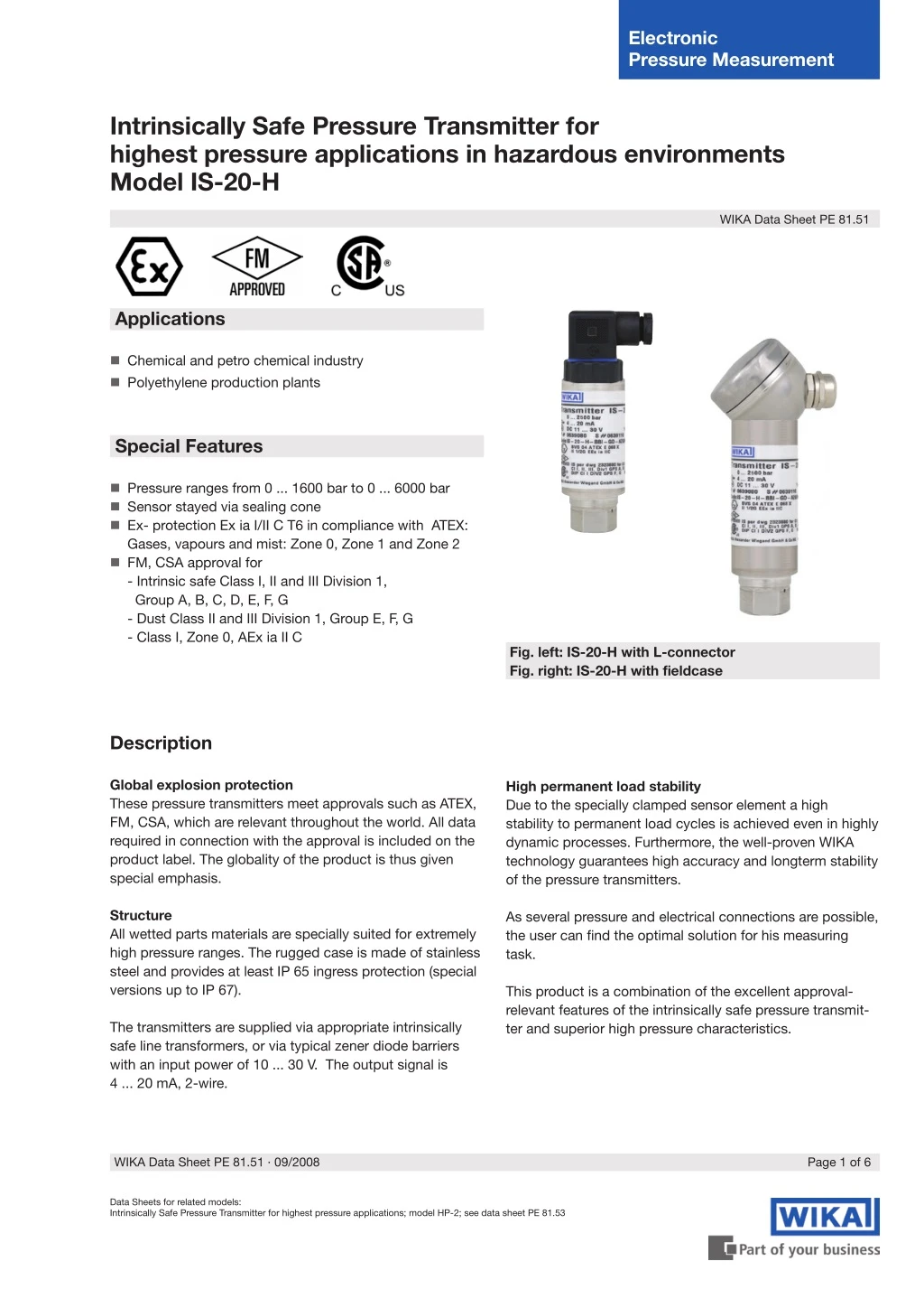
"Global explosion protection These pressure transmitters meet approvals such as ATEX, FM, CSA, which are relevant throughout the world. All data required in connection with the approval is included on the product label.<br>The globality of the product is thus given special emphasis. Structure All wetted parts materials are specially suited for extremely high pressure ranges. The rugged case is made of stainless steel and provides at least IP 65 ingress protection (special versions up to IP 67).<br>The transmitters are supplied via appropriate intrinsically safe line transformers, or via typical zener diode barriers with an input power of 10 ... 30 V. The output signal is 4 ... 20 mA, 2-wire."<br>For More Information visit on:- www.seeautomation.com<br>Our Mail I.D:- sales@seeautomation.com<br>Contact Us:- 91-11-22012324 , 8144883403

E N D
Electronic Pressure Measurement Intrinsically Safe Pressure Transmitter for highest pressure applications in hazardous environments Model IS-20-H WIKA Data Sheet PE 81.51 Applications Chemical and petro chemical industry Polyethylene production plants Special Features Pressure ranges from 0 ... 1600 bar to 0 ... 6000 bar Sensor stayed via sealing cone Ex- protection Ex ia I/II C T6 in compliance with ATEX: Gases, vapours and mist: Zone 0, Zone 1 and Zone 2 FM, CSA approval for - Intrinsic safe Class I, II and III Division 1, Group A, B, C, D, E, F, G - Dust Class II and III Division 1, Group E, F, G - Class I, Zone 0, AEx ia II C Fig. left: IS-20-H with L-connector Fig. right: IS-20-H with fieldcase Description Global explosion protection These pressure transmitters meet approvals such as ATEX, FM, CSA, which are relevant throughout the world. All data required in connection with the approval is included on the product label. The globality of the product is thus given special emphasis. High permanent load stability Due to the specially clamped sensor element a high stability to permanent load cycles is achieved even in highly dynamic processes. Furthermore, the well-proven WIKA technology guarantees high accuracy and longterm stability of the pressure transmitters. Structure All wetted parts materials are specially suited for extremely high pressure ranges. The rugged case is made of stainless steel and provides at least IP 65 ingress protection (special versions up to IP 67). As several pressure and electrical connections are possible, the user can find the optimal solution for his measuring task. This product is a combination of the excellent approval- relevant features of the intrinsically safe pressure transmit- ter and superior high pressure characteristics. The transmitters are supplied via appropriate intrinsically safe line transformers, or via typical zener diode barriers with an input power of 10 ... 30 V. The output signal is 4 ... 20 mA, 2-wire. WIKA Data Sheet PE 81.51 ∙ 09/2008 Page 1 of 6 Data Sheets for related models: Intrinsically Safe Pressure Transmitter for highest pressure applications; model HP-2; see data sheet PE 81.53
Specifications Model IS-20-H Specifications without model designation apply for all models. Pressure ranges Over pressure safety Burst pressure Materials ■ Wetted part ■ Case Power supply UB » Model IS-20-H » Model IS-20-H with fieldcase Signal output and maximum ohmic load RA » Model IS-20-H » Model IS-20-H with fieldcase Test circuit signal / max. load RA Adjustability zero/span Response time (10 ... 90 %) Power Pi Insulation voltage Accuracy bar bar bar 1600 2300 4000 2500 3500 6000 4000 5000 8000 5000 6000 10000 6000 7000 11000 Stainless steel Stainless steel UB in VDC 10 ... 30 11 ... 30 4 ... 20 mA, 2-wire RA in Ohm RA≤ (UB – 10 V) / 0.02 A - (length of flying leads in m x 0.14 Ohm) RA≤ (UB – 11 V) / 0.02 A RA≤ 15 Ohm (only model IS-20-H with fieldcase) ± 5 using potentiometers inside the instrument ≤ 1 1 (750 mW with approval for Category 1D) Insulation complies with EN 60079-11 ≤ 0.25 (BFSL) ≤ 0.5 1) 1)Including non-linearity, hysteresis, zero point and full scale error (corresponds to error of measurement per IEC 61298-2) Adjusted in vertical mounting position with lower pressure connection % of span ≤ 0.2 (BFSL) according to IEC 61298-2 % of span ≤ 0.1 % of span ≤ 0.2 (at reference conditions) % ms W % % of span Non-linearity Non-repeatability 1-year stability Permissible temperature of ■ Medium 2) 4) ■ Ambience 2) 4) ■ Storage 2) -20 ... +80 °C 3) -20 ... +80 °C 3) -30 ... +105 °C -4 ... +176 °F 3) -4 ... +176 °F 3) -22 ... +221 °F 2)Also complies with EN 50178, Tab. 7, Operation (C) 4K4H, Storage (D) 1K4, Transport (E) 2K3 3)Other temperature ranges are possible, depending on the electrical connection; see EC-type examination certificate, e.g. -30 … +105 °C / -22 … +221 °F and table page 5. 0 ... +80 °C Rated temperature range Temperature coefficients within rated temperature range ■ Mean TC of zero ■ Mean TC of range CE-conformity ■ Pressure equipment directive ■ EMC directive +32 ... +176 °F ≤ 0.2 / 10 K ≤ 0.2 / 10 K % of span % of span 97/23/EC 2004/108/EC, EN 61 326 Emission (Group 1, Class B) and Immunity (industrial locations) ■ Directive ATEX of equipment intended for use in potentially explosive atmospheres Ex-protection Ignition protection type 94/9/EC Category 4) 1/2G, 2G, M1, M2 Ex ia I/II C T4, Ex ia I/II C T5, Ex ia I/II C T6 4)Read the operating conditions and safety-relevant data in the EC-type examination certificate in any case (BVS 04 ATEX E 068 X) FM, CSA Class I, II and III Intrinsic safe Class I, II, III Division 1, Group A, B, C, D, E, F, G and Class I, Zone 0 AEx ia II C V/m 10 kV 2 g 100 according to IEC 60068-2-27 g 5 according to IEC 60068-2-6 ATEX Ex-protection Ignition protection type HF-immunity Burst Shock resistance Vibration resistance (mechanical shock) (vibration under resonance) Page 2 of 6 WIKA Data Sheet PE 81.51 ∙ 09/2008
Specifications Model IS-20-H Wiring protection ■ Short-circuit proofness ■ Reverse polarity protection Weight » Model IS-20-H » Model IS-20-H with fieldcase Sig+ towards UB- UB+ towards UB- kg kg Approx. 0.3 Approx. 0.45 { } Items in curved brackets are optional extras for additional price. Output signal and admissible load Model IS-20-H Output current (2-wire) 4 ... 20 mA, 2-wire 4 ... 20 mA: RA≤ (UB – 10 V) / 0.02 A admissible range Model IS-20-H with fieldcase Output current (2-wire) 4 ... 20 mA, 2-Leiter 4 ... 20 mA: RA≤ (UB – 11 V) / 0.02 A admissible range Relation of medium temperature to ambient temperature Calculation of operation temperatur: TB = Tmed - (Tmed - Tamb) x 0.34 TB Tmed Tamb Temperature of ambience in °C = = = Operation temperature of transmitter Max. temperature of process medium Max. temperature of ambience Max. permitted temperature of ambience: Tamb = Tmed + (TB - Tmed) / 0.34 Temperature of medium in °C WIKA Data Sheet PE 81.51 ∙ 09/2008 Page 3 of 6
Dimensions in mm Permissible temperature ranges depending on electrical connections; see table page 5. Electrical connections IS-20-H IS-20-H fieldcase Fieldcase with internal spring clip terminals, Order code: FH (threaded connection brass nickel- plated) FC (threaded connection stainless steel) ATEX: 1/2 G, M1 DIN 175301-803 A L-connector Order code: A4 ATEX: 1/2 G, M1 M 12x1 Circular connector Order code: M4 ATEX: 1/2 G, M1 *) Flying leads for conductor cross section 0.5 mm 2, AWG 20 with end splices, conductor outer diameter 6.8 mm, PUR IP 67 Order code: DL ATEX: 1/2 G, M1 Case Pressure connections M 16x1,5 female **) Order code: ML 9/16 - 18 UNF female F 250-C **) Order code: VZ M 20x1,5 female **) Order code: MP For installation and safety instructions see the operating instructions for this product. For tapped holes and welding sockets please see Technical Information IN 00.14 for download at www.wika.de -Service *) Connectors are not included in delivery. **) The respective values for your mounting position please find in the documentation of your high-pressure equipment supplier. Page 4 of 6 WIKA Data Sheet PE 81.51 ∙ 09/2008
Permissible temperature ranges depending on electrical connections Order- code Electrical connections Category Ambience-/ Medium temperature range -40 ... +60 °C (T6) -40 ... +80 °C (T5) -40 ... +105 °C (T4) -40 ... +105 °C -25 ... +60 °C (T6) -25 ... +80 °C (T5) -25 ... +90 °C (T4) -25 ... +90 °C -20 ... +60 °C (T6) -20 ... +80 °C (T5) -20 ... +80 °C (T4) -20 ... +60 °C -50 ... +60 °C (T6) -50 ... +80 °C (T5) -50 ... +105 °C (T4 -50 ... +105 °C (T4) -40 ... +140 °F (T6) -40 ... +176 °F (T5) -40 ... +221 °F (T4) -40 ... +105 °F -13 ... +140 °F (T6) -13 ... +176 °F (T5) -13 ... +194 °F (T4) -13 ... +194 °F -4 ... +140 °F (T6) -4 ... +176 °F (T5) -4 ... +176 °F (T4) -4 ... +140 °F -58 ... +140 °F (T6) -58 ... +176 °F (T5) -58 ... +221 °F (T4 -58 ... +221 °F (T4) DIN 175301-803 A L-Connector A4 1/2 G (IIC) M1 M 12x1 Circular connector M4 1/2 G (IIC) M1 Flying leads DL 1/2 G (IIC) M1 Fieldcase FH, FC 1/2 G (IIC) M1 Wiring details Wiring details L-connector DIN 175301-803 A Circular connector M12x1, 4-pin Flying leads, 1.5 m Field case (with internal spring clip terminals) 2-wire UB = 1 0V = 2 UB = 1 0V = 3 UB = brown 0V = green screen / case 0.5 mm2 (AWG 20) UB = 1 Test- = 4 0V = 2 screen = 5 Test+ = 3 Wire gauge up to max.1.5 mm2 - 6-8 mm ship approval: 10-14 mm Cable diameter - 6.8 mm (Order code: DL) 7-13 mm Ingress protection per IEC 60 529 IP 65 IP 67 IP 67 IP 67 The ingress protection classes specified only apply while the pressure transmitter is connected with female connectors that provide the corresponding ingress protection. WIKA Data Sheet PE 81.51 ∙ 09/2008 Page 5 of 6
Hazardous areas (zone classification according to ATEX) Group II: Electrical equipment for use in all areas (except mines) which are endangered by an explosive atmosphere. Zone Category Occurrence of explosive atmosphere Zone 0 Mounting to zone 0 Zone 1 Zone 2 Category 1G (gas) Category 1/2 G Category 2G Category 3G Continuous Intermittent Hazard under abnormal conditions Group I: Electrical equipment for use in mines (hazard due to mine gas) Zone Category Requirements Category M 1 Very high degree of safety High degree of safety (instruments have to be turned off if they are exposed to an explosive atmosphere) Category M 2 Hazardous areas (ATEX in comparison with FM, CSA) ATEX Group FM / CSA Class Group Gases and Vapours Dusts Fasern Gas / Dusts IIA / IIB / IIC I II III ID / IIF Above ground A / B / C / D / E / F / G Mining I Flammable material present continuously Flammable material present intermittently Flammable material normally not present ATEX FM /CSA Zone 0 Zone 0 Zone 1 Zone 1 Zone 2 Zone 2 Division 2 Zone 2 Division 1 FM (NEC505) Zone 0 Zone 1 Further information You can obtain further information (data sheets, instructions, etc.) via our internet address www.wika.de Specifications and dimensions given in this leaflet represent the state of engineering at the time of printing. Modifications may take place and materials specified may be replaced by others without prior notice. 7534705 09/2008 D Page 6 of 6 WIKA Data Sheet PE 81.51 ∙ 09/2008 WIKA Alexander Wiegand GmbH & Co. KG Alexander-Wiegand-Straße 30 63911 Klingenberg/Germany Tel. +49 / (0) 9372/132-0 Fax +49 / (0) 9372/132-406 E-mail info@wika.de www.wika.de