Download
1 / 28
280 likes | 362 Views
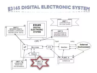
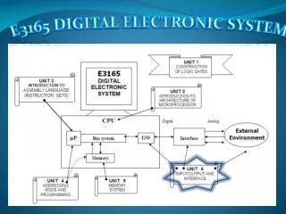
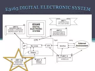
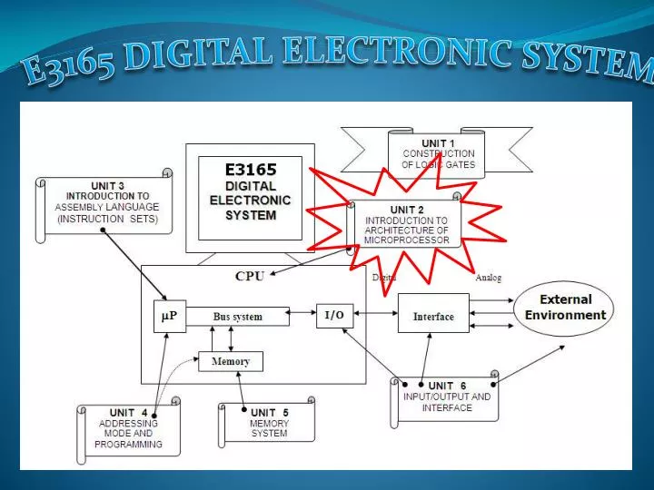
E3165 DIGITAL ELECTRONIC SYSTEM. 2.0 INTRODUCTION. Capability of processor determine the capability of the computer system. Therefore, processor is the key element or heart of a computer system.

E N D
2.0 INTRODUCTION • Capability of processor determine the capability of the computer system. Therefore, processor is the key element or heart of a computer system. • Other than PC, microprocessors are used in various computerized system such as industrial automation.
2.1 EVOLUTION OF MICROPROCESSOR • Number of bitsμP can handle at any one time determined the capacities of μP. • Improvement number of bits determined by2n.
2.1 EVOLUTION OF MICROPROCESSOR M68000 FAMILY • Comparative of various M68000 family µP. • All chips have 32 bit CPU register, but the early µP are 16 bit systems. • Why Motorola built 68008 (8 bit) after 68000 (16 bit)?
2.2 DATA SIZE • Capacity of µP: • Bits of data – size of data bus • memory size accessible – size of address bus • Data size – data stored in a single cell of memory. (size of data bus determine the data size) • 1 bit : the smallest. • 4 bit : nibble. • 8 bit : byte. • 16 bit : word. • 32 bit : longword.
2.3 BLOCK DIAGRAM OF A BASIC COMPUTER SYSTEM • Tocci, 1991 • A digital comp is a combination of digital devices and circuits that can perform a programmed sequence of operations (program) with a minimum of human intervention. • Program is a set of coded instructions, stored in the comp’s internal memory executed by the computer in order. • Comp do not think but high speed machine that can manipulate data, solve problems and make decision, all under control of the program.
2.4 BUS SYSTEM • A wire used to transfer a signal from one point to another.
2.4 BUS SYSTEM (cont.) • Data bus – bidirectional (read or write). Determine the data size. Transfer data in parallel.
2.4 BUS SYSTEM (cont.) • Address bus – unidirectional. Transfer data in parallel. Determine the number of memory cells (lines). • Control bus – bidirectional (not the same line). set of signals used to synchronize the activities of the separate microcomputer element. • Ex : Read, Write • Ex : RESET, INTR
2.5 OPERATION OF COMPUTER SYSTEM • How computer system works? • ROM permanently stores a short program (initial). • When comp is ON, CPU readprogram in ROM • 1. reset connected devices to standby mode. • 2. transfer system programs (OS) from permanent storage (hard disk) to RAM. • 3. System program will provide needs for user.
2.5 OPERATION OF COMPUTER SYSTEM (cont.) • Fetch & execute cycle
2.5 OPERATION OF COMPUTER SYSTEM (cont.) • Fetch cycle – a, b, c • Execute cycle – e
2.5 OPERATION OF COMPUTER SYSTEM (cont.) • Example 2-1 (page 28)
2.5 OPERATION OF COMPUTER SYSTEM (cont.) • Read in fetch cycle
2.5 OPERATION OF COMPUTER SYSTEM (cont.) • Write in execute cycle
2.6 INTERNAL STRUCTURE & BASIC OPERATION OF MICROPROCESSOR • Microprocessor packaged in IC chip. • The pins configuration / block diagram used to explain or analyze the architecture of a microprocessor. • Figure 2.12 – Intel 8085 microprocessor chip • Figure 2.13 – Motorola 68000 microprocessor chip
2.6 INTERNAL STRUCTURE & BASIC OPERATION OF MICROPROCESSOR • Internal structure • µP consist of : • 1. control & timing – fetch cycle, decode, execute cycle. • supply clock / timing. • 2. register – temporary. • faster than memory. • Various types. • 3. ALU – arithmetic & • logic operation.
2.6 INTERNAL STRUCTURE & BASIC OPERATION OF MICROPROCESSOR • Therefore, µP performs a number of functions, includes: • Providing timing and control signal. • Fetching instruction and data. • Decoding instruction. • Transferring data between I/O and memory. • Performing A&L operation. • Responding to I/O-generated control signal such as RESET or INTERRUPT.
2.6 INTERNAL STRUCTURE & BASIC OPERATION OF MICROPROCESSOR • Register set (32 bit) • 8 data register • 7 address register • 2 stack pointer • 1 program counter • 1 status register
2.7 MICROPROCESSOR CLOCK SYSTEM • Intel 8085 clock system and bus cycle timing
2.7 MICROPROCESSOR CLOCK SYSTEM (cont.) • Motorola 68000 clock system and bus cycle timing • Bus cycle (machine cycle)