Download
1 / 13
130 likes | 277 Views
Study of Heat Flux in a Thin Silicon MEMS Wafer with Coolant and Air Filled Regions A Finite Element Model (FEA) using flexPDE. Craig E. Nelson - Consultant Engineer. Goal for the Numerical Study

E N D
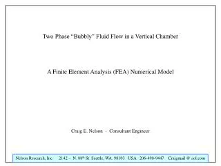
Study of Heat Flux in a Thin Silicon MEMS Wafer with Coolant and Air Filled Regions A Finite Element Model (FEA) using flexPDE Craig E. Nelson - Consultant Engineer
Goal for the Numerical Study A steady state finite element model is to be developed that aids understanding of heat flux within a silicon MEMS wafer. Heat is produced in a rectangular, constant intensity (power per unit area), source region. The heat then diffuses into the surrounding silicon regions and is carried away by cooling fluid flowing in rectangular passageways. Quadrant symmetry will be used to reduce the solution domain complexity.
Coolant Filled Region Air Boundary Air Filled Region Symmetry Boundary Air Boundary Heat Source Region Coolant Filled Region Symmetry Boundary Model Geometry
Notice “Refraction” at boundary Temperature Field - Contour Plot
Notice “Refraction” at boundary Temperature Field - Contour Plot
Region of Maximum Heat Flux Region of Maximum Heat Flux Heat Flux Field - Vector Plot
Region of Maximum Heat Flux Region of Maximum Heat Flux Heat Flux Field - Vector Plot - Normalized
Summary A steady state finite element model has been developed that aids understanding of heat flux and temperature within a silicon MEMS wafer. Heat is produced in a rectangular, constant intensity (power per unit area), source region. The heat then diffuses into the surrounding silicon regions and is carried away by cooling fluid flowing in rectangular passageways. Because the thermal conductivity is different in different regions, the resultant temperature field is complex and interesting. Quadrant symmetry was used to reduce the solution domain complexity.