Download
1 / 44
440 likes | 593 Views
Qualification Test of a MPPC-based PET Module for Future MRI-PET Scanners. Yohta KUREI J.Kataoka , T.Kato , T.Fujita , H.Funamoto , T.Tsujikawa ( Waseda Univ .) S.Yamamoto (Nagoya Univ.). 5 September 2013 9 th International “Hiroshima” Symposium

E N D
Qualification Test of a MPPC-based PET Module for Future MRI-PET Scanners Yohta KUREI J.Kataoka, T.Kato, T.Fujita, H.Funamoto, T.Tsujikawa (Waseda Univ.) S.Yamamoto (Nagoya Univ.) 5 September 2013 9th International “Hiroshima” Symposium @ International Conference Center Hiroshima, Japan
2 Contents PET and Detectors Evaluation of images by PET Evaluation of images by MRI Future prospects and summary
3 Positron Emission Tomography Warburg effect :glucose • Cancer cells like glucose ⇒ FDG + glucose isotope tracer DoI normal cell cancer cell Isotope is accumulated in cancer ToF • Functional imaging with 511keV annihilation gamma-ray • Time of Flight(ToF) informationimprove S/N • Depth of Interaction(DoI) information improve image quality Cancer
4 Characteristics of Modalities • CT-PET = already being made into a product • becoming common as a multimodality imaging device • internal and external exposure • MRI-PET • ToF-PET,DoI-PET • No problem of extra exposure ⇒compactness, low power and ⇒insensitivity to B fields is required high time resolution are required
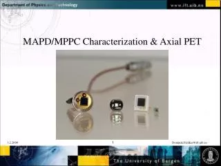
5 Detectors PMT is incorporated in conventional PET scanner • high gain • long history and proven PMT ex.)Super-Kamiokande However, PMT is … Scintillator • intricate in construction • large size • sensitive to B fields 13.6mm SD can overcome these points 13.6mm PD, APD : compact semiconductor MPPC : 2D-array of Geiger-mode APDs especially, MPPC has great characteristics
6 Characteristics of Detectors suitable for PET • High gain(= doesn’t need CSA) ⇒much betterS/N ⇒much better time resolution (suitable for ToF-PET) • Compact and simple structure ⇒suitable for DoI-PET
7 Our PET Project w/ MPPC Patent application PCT/JP2012/008129 (Waseda Univ., Furukawa K.K.) DoI technique Kishimoto et al. 2013, IEEE sandwich scinti b/w MPPCs 1mm cube ⇒ K.Takeuchi’s talk yesterday (Compton Camera) • widely varying use ToF technique Average jitter; 105ps(FWHM) Time resolution; 616ps(FWHM) ⇒ T.Ambe’s Poster
8 Characteristics of Detectors • No Interfered in static magnetic fields ⇒ Can “future MRI-PET” apply?
9 Qualification Test • image by PET operating with the MRI influenced from MRI • Phantom image by MRI operating with the PET influenced from MPPC ≪experiment environment≫ BioView Inc. MRI: Varian INOVA UNITY 4.7 T MRI (gradient coil: 10 gauss/cm)
10 Test1: Imaging by PET static magnetic coil recieveresponce gradient coil linear info. MPPC condition • Outside MRI • Inside MRI(under FSE) • Inside MRI(under GE) Left: MPPC array Hamamatsu S11827-3344MG Right: Ce:LYSO 12×12 array (1.0×1.0×10mm3 ) source FSE,GE: procedures for taking MR image RF coil MPPC+LYSO
11 Result of Test1: Imaging by PET FSE outside GE
12 Result of Test1: Imaging by PET Projection X(FWHM) FSE 1.65±0.07 mm 1.63±0.03 mm outside GE 1.70±0.08 mm
13 Result of Test1: Imaging by PET FSE outside GE
14 Result of Test1: Imaging by PET Projection Y(FWHM) FSE 1.49±0.05 mm 1.48±0.03 mm outside GE 1.55±0.13 mm
15 Test2: Imaging by MRI (1) inside MRI(MPPC powered on) (2) inside MRI(MPPC powered off) (3) removeMPPC SliceNo.1~5 Slice No.1~5 Before(left) and after(right) removing the probe No.1 No.2 No.3 No.4 No.5 Images(Cooperation:BioView Inc.) (1) (2) (3)
16 Result of Test2: Imaging by MRI power ON (red line) power OFF (green line) remove MPPC (blue line)
17 Result of Test2: Imaging by MRI Loss Ratio Only 5% Loss Loss Ratio=(Power ONor OFF)/(Remove the Probe)×100 [%]
18 Result of Test2: Imaging by MRI Power on1 How much noise ? Only 6(noise) w.r.t. 255(signal) Power off1
19 Future prospects • PET/MRI have littleimpact on MRI/PET A more advanced version of the MRI-PET gantry with 8 MPPC-based PET modules
20 Summary • We developed a high resolution, compact PET module for future MRI-PET scanners • A slight degradation in the spatial resolutions of PET image operating with MRI • Signal Loss Ratio of MR image was only degraded by 5% operating with PET • Noise of MR image was only a few percent • We’re developing a more advanced version of the MRI-PET gantry with 8 MPPC-based PET modules
Appendix: DoI Technique Patent application PCT/JP2012/008129 (Waseda Univ., Furukawa K.K.) Kishimoto et al. 2013, IEEE DoI position 1mm cube 3mm cube 2mm cube
:FFC 2m(signal) :Coax Cable5m(HV) Connector Plastic Case Connector Plastic Case Circuit FFC, CC→LEMO Alumi. Case MPPC Plastic Case No magnetic fields magnetic fields
1. draw flood MAP • 2. create LUT • 3. select 511keV in LUT create image by using the selecting events
5V power supply • temperature compensation circuit • HV ×4 • MPPC • Fan I/O • Fan I/O ×16 ×4 • Delay • Discri. • CSADC • Coincidence • G&D Generator • Gate • Delay • Discri. • HV ×4 • G&D Generator • MPPC • Fan I/O • Fan I/O ×4 • D I/O ×16
The principle of MRI. What is Fast Spin/Gradient Echo?
N apply static magnetic field into protons Axial directions and phases are parallel and start to precess S
N apply RF waves into protons RF proton receive the energy and leanby RF waves (excitation state) S
N stop applying RF waves into protons : electromagnetic ray(FID signal) start to return parallel state and radiate energy in the form of e.m. rays RF S
animation A) All are vertical in the vertical magnetic field and spinning on their long axis, but this illustration is in a rotating reference frame where the spins are stationary on average. B) A 90 degree pulse has been applied that flips the arrow into the horizontal (x-y) plane. C) Due to local magnetic field inhomogeneities, as the net moment precesses, some spins slow down due to lower local field strength while some speed up due to higher field strength and start getting ahead of the others. This makes the signal decay. D) A 180 degree pulse is now applied so that the slower spins lead ahead of the main moment and the fast ones trail behind. E) The fast moments catch up with the main moment and the slow moments drift back toward the main moment. F) Complete refocusing has occurred and at this time the echo can be measured.
FSE:90 deg pulse +180 deg pulse RF wave incline proton at a 90 deg angle RF wave the slower spins lead ahead of the main moment and the fast ones trail behind. GE:α deg pulse + inverse gradient α (≦90deg) shorten the time of incline gradient magnetic field reversal No Pulse = more shorter time FSE:a few minutes GE:a few seconds We want to receive FID signal, but we can’t because the signal decay very fast. (This problem is caused by magnetic field inhomogeneity.) Then, we repeat applying 180deg pulse into proton after 90deg pulse. and then the echo of resonance signal is occurred.
spectrum under B field (S10362-33-050C) (Not array)
spectrum under B field (S10362-33-050C) 3 kinds of circuit inside MRI + copper shield outside MRI inside MRI in static magnetic fields under FSE under GE MPPC is compared to outside MRI • check the waveform by OSC • evaluate each E resolution
5V power supply • temperature compensation circuit • HV • MPPC • Fan I/O • Discri. • G&D Generator • Gate • Delay • G&D Generator • CSADC • D I/O filter circuit
FSE,GEによるノイズ pulse FSE outside MRI 511 keV pulse GE 511 keV no interference by set up discriably
circuit is inside MRI copper shield outside MRI inside MRI MPPC is outside MRI Grand Level static magnetic fields
circuit is inside MRI copper shield outside MRI inside MRI MPPC is outside MRI Grand Level FSE
circuit is inside MRI copper shield outside MRI inside MRI MPPC is outside MRI Grand Level GE
circuit is inside MRI copper shield outside MRI inside MRI MPPC is outside MRI 511keV static magnetic fields
circuit is inside MRI copper shield outside MRI inside MRI MPPC is outside MRI 511keV FSE
circuit is inside MRI copper shield outside MRI inside MRI MPPC is outside MRI 511keV GE
E resolution energy resolution(511keV, FWHM)