Download
1 / 35
380 likes | 541 Views
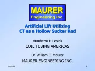
Artificial Lift Utilizing CT as a Hollow Sucker Rod. Humberto F. Leniek COIL TUBING AMERICAS Dr. William C. Maurer MAURER ENGINEERING INC. Stekoll Slimhole Pumping System (1960). 1” Tee. Rubber Hose. Clamp. Flow Line. Conventional Stuffing Box. Polished Rod Liner. Gas Vent.

E N D
Artificial Lift UtilizingCT as a Hollow Sucker Rod Humberto F. Leniek COIL TUBING AMERICAS Dr. William C. Maurer MAURER ENGINEERING INC.
Stekoll Slimhole Pumping System (1960) 1” Tee Rubber Hose Clamp Flow Line Conventional Stuffing Box Polished Rod Liner Gas Vent 2 7/8” Casing 1” EUE Pumping String Blind Cage Traveling Barrel Insert Pump Slip-Type Hold-Down with Rubber Removed Screen
STEKOLL Field Experience (1960) • Over 1,000 Wells • 3,000 to 5,000 Foot Wells • 1” EUE Tubing (Hollow Sucker Rod) • 2-1/2” & 2-7/8” Inch Casing • 70 BOPD • 40 to 50% Reduction in Tubular Costs • 17% Overall Cost Savings
STEKOLL Slimhole Wells (1960) • Bolton Field, Kansas (1,000 ft) - 1,000 Wells • Corsicana, Texas (1,200 ft) - 300 Wells • Panhandle, Texas (3,000 ft) - 20 Wells • Canada (5,000 ft) - 15 Wells
STEKOLL Slimhole Operations (2-7/8”) • Drilling & Logging • Perforating & Squeeze Cementing • Acidizing & Fracturing • Fishing & Washovers • Sand Bailing • Dual Completions
Hollow Sucker Rod Advantage • “The hollow sucker rod combines the function of the sucker rod and the tubing, so it is no longer necessary to pull both sucker rods and tubing when working over wells.” • STEKOLL, 1960
STEKOLL System Limitations (1960) • Limited Slimhole Logging Tools • Workover Concerns • Tubing Failures • Resistance to Slimholes • Resistance to New Technology
Leniek Pumping System (1999) 1-1/2” Hydraulic Hose Clamp Production Line Stuffing Box Hollow Polish Rod Gas Vent 2-7/8” or 3-1/2” Casing (CT or Tubing) 1-1/2” Coiled Tubing Hollow Rod Pump Anchor Screen
Leniek CT Pumping System • Conventional Surface Equipment • 1,000 to 5,000 Feet • 2-7/8” or 3-1/2” Casing (CT or Tubing) • 1-1/2” CT (Hollow Sucker Rod) • Hollow Polish Rod • Hollow Rod Pump
“U” Tube Bridel Hydraulic Connector Polish Rod Clamp Dynamometer Holder 1-1/2” Hydraulic Hose Production Line Hollow Polish Rod Lubricated Stuffing Box Leniek Surface Equipment (1999)
Leniek Bottomhole Assembly Gas Gas 2-7/8” or 3-1/2” Casing (CT or Tubing) Oil 1-1/2 Coiled Tubing Anchor Perforations Hollow Rod Pump Screen Oil
Sucker Rod Pumps Pull Rod Coiled Tubing Tubing Tubing Pump Barrel Hollow Pull Rod Pump Plunger Pump Plunger Traveling Valve Pump Barrel Traveling Valve Pump Barrel Conventional Seating Nipple Anchor Standing Valve Standing Valve Conventional Hollow Rod
Leniek System Advantages • Reduce Well Construction Cost 50 Percent • Eliminates Tubing Thread Failures • Eliminates Tubing Anchors • Reduce Lifting Costs • Reduce Paraffin Problems • Reduce Casing Wear • Treat Wells Through CT • Eliminate Rod Failures • Allows Ultraslim Holes
Initial Concerns • CT Fatigue Failures • CT Buckling • CT Wear • Casing Wear
Argentina YPF Test(1998-1999) • San Jorge Basin • 2,600 Foot Well • 60 BPD • 2-7/8” Casing (Tubing) • 1-1/2” CT • 13 Months (No Failures)
Coiled Tubing Pumping Fatigue Model CT Length (ft) Years to Failure 1000 1207 1414 1621 1828 2034 2241 2448 2655 2862 3069 3276 3483 3690 3897 4103 4310 4517 4724 4931 5138 5345 5552 5759 5966 6172 6379 6586 6793 7000 >30 >30 >30 >30 >30 >30 >30 >30 >30 >30 >30 >30 >30 >30 >30 >30 >30 >30 >30 >30 >30 >30 >30 >30 >30 >20 >10 7.61 4.64 2.87 Acceptable Project Name: Well Name: CT OD (in): CT Wall Thickness (in): Casing Pipe OD (in): Casing Pipe Weight (lb/ft): CT Yield Strength (psi): CT Weld Reduction Factor: Stress Concentration Factor: Fatigue Strength Coefficient: Pumping Fluid Density (ppg): CT Job Corrosion Factor: Stroke Rate (stk/min): Pumping Stroke Length (in): CT Length (ft): CTPS XYZ 1.500 0.1340 3.500 9.380 100000 1 1 125000 8.33 1 6 74 6000
Leniek Potential Applications • Marginal Oilfields • Shallow Wells • Low Production Wells (<300 BOPD) • Close Well Spacing • In Fill Drilling • Drill New Wells With Smaller Drilling Rigs
Leniek Marketing Options • Start Service Company • Form Alliances with Service Companies • License Patent Rights to Service Company • Sell Territorial Rights to Operators • Form Partnership With Major Independent • Drill Slimholes Free For Oil Participation • Purchase Shallow Fields and Become Operator
The End Visit our web site: www.maureng.com
Installation & Workover Requirements • CT Rig • New CT • Good Supervision
Future Requirements • CT Centralizers • Low Cost CT Pulling Units • Trained Personnel • Industry Acceptance • Service Company Supplier
Coiled Tubing Pumping Fatigue Model CT Length (ft) Years to Failure 1000 1207 1414 1621 1828 2034 2241 2448 2655 2862 3069 3276 3483 3690 3897 4103 4310 4517 4724 4931 5138 5345 5552 5759 5966 6172 6379 6586 6793 7000 >30 >30 >30 >30 >30 >30 >30 >30 >30 >30 >30 >30 >30 >30 >20 >10 6.66 3.82 2.25 1.35 0.83 0.52 0.33 0.22 0.14 0.09 0.06 0.04 0.03 0.02 Acceptable Project Name: Well Name: CT OD (in): CT Wall Thickness (in): Casing Pipe OD (in): Casing Pipe Weight (lb/ft): CT Yield Strength (psi): CT Weld Reduction Factor: Stress Concentration Factor: Fatigue Strength Coefficient: Pumping Fluid Density (ppg): CT Job Corrosion Factor: Stroke Rate (stk/min): Pumping Stroke Length (in): CT Length (ft): CTPS XYZ 1.500 0.1340 2.875 5.059 80000 1 1 105000 8.33 1 6 74 4000
Coiled Tubing Pumping Fatigue Model CT Length (ft) Years to Failure 1000 1207 1414 1621 1828 2034 2241 2448 2655 2862 3069 3276 3483 3690 3897 4103 4310 4517 4724 4931 5138 5345 5552 5759 5966 6172 6379 6586 6793 7000 >30 >30 >30 >30 >30 >30 >30 >30 >30 >30 >30 >30 >10 8.55 4.48 2.43 1.35 0.78 0.46 0.27 0.17 0.11 0.07 0.04 0.03 0.02 0.01 0.01 0.01 0.00 Unacceptable Project Name: Well Name: CT OD (in): CT Wall Thickness (in): Casing Pipe OD (in): Casing Pipe Weight (lb/ft): CT Yield Strength (psi): CT Weld Reduction Factor: Stress Concentration Factor: Fatigue Strength Coefficient: Pumping Fluid Density (ppg): CT Job Corrosion Factor: Stroke Rate (stk/min): Pumping Stroke Length (in): CT Length (ft): CTPS XYZ 1.500 0.1340 3.500 9.380 80000 1 1 105000 8.33 1 6 74 4000
Coiled Tubing Pumping Fatigue Model CT Length (ft) Years to Failure 1000 1207 1414 1621 1828 2034 2241 2448 2655 2862 3069 3276 3483 3690 3897 4103 4310 4517 4724 4931 5138 5345 5552 5759 5966 6172 6379 6586 6793 7000 >30 >30 >30 >30 >30 >30 >30 >30 >30 >30 >30 >30 >30 >30 >30 >30 >30 >20 >10 8.53 4.88 2.85 1.70 1.03 0.64 0.40 0.26 0.17 0.11 0.07 Acceptable Project Name: Well Name: CT OD (in): CT Wall Thickness (in): Casing Pipe OD (in): Casing Pipe Weight (lb/ft): CT Yield Strength (psi): CT Weld Reduction Factor: Stress Concentration Factor: Fatigue Strength Coefficient: Pumping Fluid Density (ppg): CT Job Corrosion Factor: Stroke Rate (stk/min): Pumping Stroke Length (in): CT Length (ft): CTPS XYZ 1.500 0.1340 3.500 9.380 90000 1 1 115000 8.33 1 6 74 4000
Coiled Tubing Pumping Fatigue Model CT Length (ft) Years to Failure 1000 1207 1414 1621 1828 2034 2241 2448 2655 2862 3069 3276 3483 3690 3897 4103 4310 4517 4724 4931 5138 5345 5552 5759 5966 6172 6379 6586 6793 7000 >30 >30 >30 >30 >30 >30 >30 >30 >30 >30 >30 >30 >30 >30 >30 >30 >30 >10 7.70 3.88 2.01 1.07 0.58 0.33 0.19 0.11 0.06 0.04 0.02 0.01 Unacceptable Project Name: Well Name: CT OD (in): CT Wall Thickness (in): Casing Pipe OD (in): Casing Pipe Weight (lb/ft): CT Yield Strength (psi): CT Weld Reduction Factor: Stress Concentration Factor: Fatigue Strength Coefficient: Pumping Fluid Density (ppg): CT Job Corrosion Factor: Stroke Rate (stk/min): Pumping Stroke Length (in): CT Length (ft): CTPS XYZ 1.750 0.1560 5.500 14.500 100000 1 1 125000 8.33 1 4 74 6000
Coiled Tubing Pumping Fatigue Model CT Length (ft) Years to Failure 1000 1207 1414 1621 1828 2034 2241 2448 2655 2862 3069 3276 3483 3690 3897 4103 4310 4517 4724 4931 5138 5345 5552 5759 5966 6172 6379 6586 6793 7000 >30 >30 >30 >30 >30 >30 >30 >30 >30 >30 >30 >30 >30 >30 >30 >30 >10 7.57 3.70 1.87 0.97 0.52 0.28 0.16 0.09 0.05 0.03 0.02 0.01 0.01 Acceptable Project Name: Well Name: CT OD (in): CT Wall Thickness (in): Casing Pipe OD (in): Casing Pipe Weight (lb/ft): CT Yield Strength (psi): CT Weld Reduction Factor: Stress Concentration Factor: Fatigue Strength Coefficient: Pumping Fluid Density (ppg): CT Job Corrosion Factor: Stroke Rate (stk/min): Pumping Stroke Length (in): CT Length (ft): CTPS XYZ 1.750 0.1560 5.500 14.500 100000 1 1 125000 8.33 1 6 74 4000
Flexible Rubber Hose to Oil Lead Line Hollow Polish Rod Gas Vent Conventional Stuffing Box Production Tee 2-7/8” J-55 Non Upset Seamless Tubing Set As Casing 1” J-55 External Upset Seamless Tubing Used as Sucker Rods 1” J-55 External Upset Seamless Tubing Used as Sucker Rods
Elbow Hose Fast Connector Hollow polished rod Stuffing box Check valve Production line Pressure relief or chemical inlet Ground level Surface casing 5-1/2 Casing Perforations 2-7/8 Tubing 1-1/2 Coiled tubing Pump Pump seat Tubing anchor
Sucker Rod Pump in Horizontal Well Pump Jack Pump (30O inclination) Pump (90O inclination) 100-200 ft. Oil