Download
1 / 56
560 likes | 596 Views
Unicast Routing in IPv6. Babu Ram Dawadi. Unicast Routing Protocol. Unicast routing is a process that enable sender to send an unicast IP packets to the destination node. 1 router or more intermediate routers may be used, depending to the destination of the node. (Figure 1)

E N D
Unicast Routing in IPv6 Babu Ram Dawadi
Unicast Routing Protocol • Unicast routing is a process that enable sender to send an unicast IP packets to the destination node. • 1 router or more intermediate routers may be used, depending to the destination of the node. (Figure 1) • Unicast routing protocol is a set of rules of forwarding unicast traffic from a source to a destination on an internetwork. The router is using only 1 port to forwards the received unicast packet Fig. 1. Unicast Routing
Routing Interior Exterior RIP OSPF BGP Unicast Routing Protocol • Unicast Routing Protocol consists of: • RIP (Routing Information Protocol) • OSPF ( • BGP • They each serve a different purpose. Fig. 2. Types of Unicast Routing Protocol
RIPng (RFC 2080) • Based on Distance Vector algorithm known as bellman ford algorithm • Router keeps the following entries in the routing table • IPv6 Route • Address prefix and prefix length of the destination address • Next Hop Address • The IPv6 Address (link-local) of the first router along the path • Next Hop Interface • The physical interface used to reach the next hop • Metric • Number indicating the total distance to the destination. RIPng advertizes directly connected routes with the configured outgoing metric of 1
RIPng routing table • Timer • Amount of time since the information about the route was last updated • Route change flag • Set to control triggered routing updates • Route Source • Entity to provide route information eg: Ripng, OSPF etc..
RIPng Message Format • UDP based protocol using udp port number 521 20 Bytes/RTE 1: Request 2: Response • Command 1: ask system to send all or part of its routing table • Command 2: sends an update message containing all or parts of the senders routing table. Command 1B Version 1B Unused 2B
Routing Table Entry (RTE) • RIPng header is followed by one or more routing table entries (format of Routing table entry) 16 B IPv6 Prefix 2 B Route Tag 1 B Prefix Length 1 B Metric(1-16)
RTE.. • Route Tag • It may be used to carry additional information about a route learned from another routing protocol eg: BGP • The number of RTEs within single updates depends on the MTU of the medium between two neighboring routers • No of RTEs=[INT(MTU-IPv6 Hdrlen-UDP Hdrlen -RIPngHdrlen) / RTE-Size] • Timers • RIPng uses different timers to control updates of the routing information • Update timer • By default, every 30 seconds, RIPng process wakesup on each interface to send an unsolicited routing response to the neighboring routers
Timer • Timeout Timer • Each time a route entry is updated and the timeout timer is reset to zero • If the route entry reaches 180 secs (default), without another update, it is considered to have expired, metric set to 16 and garbage collection process starts • Garbage collection timer (hold down timer) • Set to 120 secs (default) that have timeout or been received with a metric of 16 after expiration, the route entry finally be removed from the routing table.
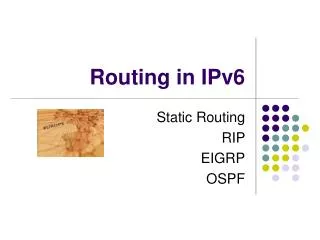
OSPF • The difference between intra-domain and inter-domain (Fig. 2.) • Routing within the same AS (Autonomous System) is referred to as intra-domain. • Routing in the different AS (Autonomous System) is referred to as inter-domain. • OSPF is an interior routing protocol • Intra-domain routing protocol a) Intra-domain b) Inter-domain Fig. 3. Interior Routing Protocol
OSPF Header 40Byte 16 Byte RouterID 4B Version 1B AreaID 4B Packet Type 1B Checksum 2B Packet Length 2B Instance ID 1B Unused 1B
OSPF Process • Link State routing • Each node within the autonomous system has the information about the entire topology. • Each node in the domain build up the routing table using Dijkstra’s algorithm. • Link State Database (LSDB) contains link state advertisement is send to every router in the same domain. • Each router will be updated with the latest copy of LSDB • Based on the LSDB, router creates a Shortest Path First (SPF) tree • Using Dijkstra’s a Algorithm • A routing table can be derived from the SPF tree which contains the best route to each router.
OSPF Packets Type 1 Type 2 Type 3 Type 5 Type 4 Link State Acknowledgement HELLO Database Description Link State Request Link State Update Router Link 0x2001 Network Link 0x2002 Inter-Area-Prefix LSA 0x2003 Inter-Area-Router LSA 0x2004 AS-External-LSA 0x4005 Group- Membership-LSA 0x2006 Type-7-LSA 0x2007 Link-LSA 0x0008 Intra-Area-Prefix LSA 0x2003 Types of OSPF Packets Fig. 4. Types of OSPF Packet
How do OSPF routers on the same link establish adjacencies? What does it mean to be adjacent? GWE.
OSPF- Forming Adjacencies • OSPF routers on the same link establish adjacencies • Using Hello packet • An OSPF router need to go through 7 steps from no connection to full adjacency when it is first initialized. • Down State • Init State • Two Way state • Exstart • Exchange State • Loading State • Full Adjacency
OSPF- Forming Adjacencies (cont) None Down State No information has yet been exchanged. Hello Packet (Type 1) Init State Routers send hello packets at regular intervals to establish relationships. Two-way State Hello Packet (Type 1) A router sees itself in a hello packet. Hello Packet (Type 1) Exstart Routers negotiate master/slave relationship by comparing their router id using hello packets. Exchange State Database Description (Type 2) Neighbors start communicating their link-state information with the others. Loading State Link State Request Link State Update Link State Acknowledgement (Type 3,4,5) The router has the initial information of each route, they may request for more complete information. Full All (Type 1,2,3,4,5) Routers are fully adjacent.
OSPF- Forming Adjacencies (cont) • Processing of Hello packet Fig. 5. Processing a Hello Packet (Reference: IPv6 Essential Pg.169)
OSPF- Forming Adjacencies (cont) The first OSPF neighbor is Down state. It means that no information (hellos) has been received from this neighbor. But it still can send Hello message to its neighbours Router 2 has received a hello packet from its neighbor, but the receiving router's ID was not included in the hello packet Router1 has seen the Router 2’s hello packet which had included its own Router ID within the received hello packet's neighbor field Router2 also has received the Router 1’s hello packet which had also included its own Router ID within the received hello packet's neighbor field • Forming an adjacency • Phases • Packet type involved • At this state, a router decides whether to become adjacent with this neighbor. • The decision on adjacencies is always depend on the link media. (Types of network) • Point to Point • No DR/BDR is needed or used because • because only 2 neighbour routers. • Broadcast Multiple Access • -DR and BDR are elected. • Non-Broadcast Multiple Access • -DR and BDR are elected To Be Continue... Time Fig. 6. Forming an Adjacencies – Part I (Reference: IPv6 Essential Pg.170)
OSPF- Forming Adjacencies (cont) • Types of Network: Broadcast Multiple Access Ethernet, Token Ring Point to Point PPP, HDLC Non Broadcast Multiple Access (NBMA) X.25, Frame Relay Fig. 7. Types of Network
OSPF- Forming Adjacencies (cont) • When DR and BDR are elected, we can say that the adjacencies was established. • The DR and BDR are elected based on several criteria • DR – with highest router ID • BDR – with second highest router ID • Priority 0 will never be DR or BDR • If priorities are same, the higher Router ID is elected. • If DR fails, BDR becomes DR, and new BDR is elected. • After adjacent, the routers already created reliable channels to their neighbors. • These reliable channels is important for the routers to exchange Link State Database (LSDB) with the neighbors..
OSPF - Link State Databases The Router 1 is attempted to start the Exchange because “he” might thought that “he” has the highest Router ID • When the routers have elected DR and BDR, the databases need to get synchronized • Routers enter ExStart • Decide who is the Master and Slave. • Router with the Highest ID will become Master and only this router can increment the sequence number • The Master/Slave election is on a per-neighbor basis • Master/Slave election is irrelevant to DR/BDR election for a network. But Router 2 will reply “No”. I will start the Exchange State first, because I have a higher Router ID After the election of Master and Slave, the routers start exchange database descriptor (DBD) packets. !But your DR/BDR election might be purely based on the higher priority configure on router !It might logic to conclude that the DR/BDR with the highest Router ID will become the master during this process of master/slave election. Each DBD packet has a sequence number which can be incremented only by master and explicitly acknowledged by slave DBD contain link-state advertisement (LSA) headers only and describe the contents of the entire link-state database In this state, the actual exchange of link state information occurs Routers are fully adjacent with each other. All the router and network LSAs are exchanged and the routers' databases are fully synchronized. Based on the information provided by the DBDs, routers send link-state request packets The neighbor then provides the requested link-state information in link-state update packets Fig. 7. Forming an Adjacencies-Part II (Reference: IPv6 Essential Pg.170)
OSPF – Database Description (DBD) Packet OSPF Packet Type 2 Database Description Packet Database Description fields: I bit = Init bit M bit = More bit MS bit = Master / Slave bit
OSPF – Database Description (DBD) Packet I bit is set to1 Indicate that this is First DBD packet send by this router 172.16.51.3 This packet contain no data. M bit is set to 1 Indicate that there are more DBD packets to follow MS bit is set to 1 Indicate that this router (172.16.51.3) declares itself to be Master
OSPF – Database Description (DBD) Packet I bit is set to 1 Indicate that this is First DBD packet send by this router 202.249.25.234 This packet contain no data. M bit is set to 1 Indicate that there are more DBD packets to follow MS bit is set to 1 Indicate that this router (202.249.25.234) declares itself to be Master Empty
OSPF – Database Description (DBD) Packet I bit is set to 0 Indicate that this is NOT First DBD packet send by this router 172.16.51.3. It contain database description of router 172.16.51.3 M bit is set to 0 Indicate that there are no more DBD packets to send All database descriptions have been sent MS bit is set to 0 Indicate that this router (172.16.51.3) declares itself to be Slave
OSPF – Database Description (DBD) Packet I bit is set to 0 Indicate that this is NOT First DBD packet send by this router 202.249.25.234 It contain database description of router 202.249.25.234 M bit is set to 1 Indicate that there are more DBD packets to send The database descriptions will still be sent MS bit is set to 1 Indicate that this router (202.249.25.234) is still a Master
OSPF – Database Description (DBD) Packet The router 172.16.51.3 is still sending a empty packet even it had no data description to send. This empty packet is help to keep the DBD sequence number matched because router 202.249.25.234 is still sending the DBD packet. I bit is set to 0 Indicate that this is NOT First DBD packet send by this router 172.16.51.3. It contain database description of router 172.16.51.3 M bit is set to 0 Indicate that there are no more DBD packets to send All database descriptions have been sent MS bit is set to 0 Indicate that this router (172.16.51.3) is still a Slave Empty
OSPF – Database Description (DBD) Packet I bit is set to 0 Indicate that this is NOT First DBD packet send by this router 202.249.25.234 It contain database description of router 202.249.25.234 M bit is set to 0 Indicate that there are no more DBD packets to send All database descriptions have been sent MS bit is set to 1 Indicate that this router (202.249.25.234) is still a Master
OSPF – Database Description (DBD) Packet Now, both router has nothing more to send All the router now enter to the Loading State I bit is set 0 Indicate that this is NOT First DBD packet send by this router 172.16.51.3. M bit is set 0 Indicate that there are no more DBD packets to send All database descriptions have been sent MS bit is set 0 Indicate that this router (172.16.51.3) is still a Slave Empty
OSPF – Link State Request Packet OSPF Packet Type 2 Link State Request Packet Multiple requests can be sent using a single packet. (Reference IPv6 Essential pg.172)
OSPF – Link State Update Packet (0x2001) OSPF Packet Type 4 Link State Request Packet Link State Update Packet Type 0x2001 Router-LSA
OSPF – Link State Update Packet (0x2002) OSPF Packet Type 4 Link State Request Packet Link State Update Packet Type 0x2002 Network-LSA
OSPF – Link State Update Packet (0x4005) OSPF Packet Type 4 Link State Request Packet Link State Update Packet Type 0x4005 AS-External-LSA
OSPF Packet Type 4 Link State Request Packet Link State Update Packet Type 0x0008 Link-LSA Purpose: List all IPv6 Prefix attached to the link OSPF – Link State Update Packet (0x0008)
OSPF – Link State Update Packet (0x2009) Each Link Update Request must be Acknowledged by Link State Acknowledgment Packet OSPF Packet Type 4 Link State Request Packet Link State Update Packet Type 0x2009 Intra-Prefix-LSA
OSPF Packet Type 5 Link State Acknowledgement Packet OSPF – Link State Acknowledgement Packet All the router now enter the Full State Hello packet is still sending to keep the adjacency alive
Learn how to see the above processes using ospfd, and ospf6d.
This command shows the interface configuration parameter such as costs, priority, DR/BDR for this interface, and Status. Example: OSPF Interface Information
This command shows all neighbors connected to the node and their status. Example: Neighbours
The type of LSA can be specify from the command and these is the 8 types of the LSA packet. Example: Link State Database
This is the LSA database summary. Example: Link State Database (cont)
This is the SPF Tree information. The SPF tree is used to calculate the shortest path from each node to all other nodes in the area. Example: Shortest Path Tree
Where is ospf6d process? The telnet to OSPF failed because the process of OSPF6D was not running Case 1 : Unable telnet to OSPF
ospf6d process The telnet to OSPF success because the process of OSPF6D was running Case 1 : Successfully Telnet to OSPF
Changing the rl0 MTU size to be 1500 bytes for OSPF6D Case 2: Unable to enter Full State with DR in OSPF
Adjacency always stay at ExStart State and will never proceed to Full State Case 2: Unable to enter Full State with DR in OSPF
From the ospf6d.log file, we can see that the adjacency with DR was stuck at Exstart State Case 2: Unable to enter Full State with DR in OSPF