Download
1 / 37
390 likes | 532 Views
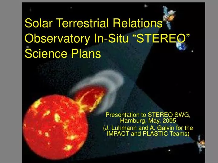
Solar Terrestrial Relations Observatory In-Situ “STEREO” Science Plans. Presentation to STEREO SWG, Hamburg, May, 2005 (J. Luhmann and A. Galvin for the IMPACT and PLASTIC Teams). STEREO Science Objectives. Understand the causes and mechanisms of CME initiation

E N D
Solar Terrestrial Relations Observatory In-Situ “STEREO” Science Plans Presentation to STEREO SWG, Hamburg, May, 2005 (J. Luhmann and A. Galvin for the IMPACT and PLASTIC Teams)
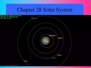
STEREO Science Objectives • Understand the causes and mechanisms of CME initiation • Characterize the propagation of CMEs through the heliosphere • Discover the mechanisms and sites of energetic particle acceleration in the low corona and the interplanetary medium • Develop a 3D time-dependent model of the magnetic topology, temperature, density, and velocity structure of the ambient solar wind
Mission Orbit 4 yr. 3 yr. Ahead @ +22/year 2 yr. 1 yr. Sun Sun Earth 1yr. Ahead Behind @ -22/year Earth 2yr. Behind 3 yr. 4 yr. Heliocentric Inertial Coordinates (Ecliptic Plane Projection) Geocentric Solar Ecliptic Coordinates Fixed Earth-Sun Line (Ecliptic Plane Projection)
STEREO IN-SITU INSTRUMENTS • IMPACT- will sample the 3-D distribution of solar wind plasma electrons, the characteristics of the energetic particle ions and electrons, and the local magnetic field. • Solar Wind Experiment (SWEA)-Measures ~0-3 keV electrons with wide angle coverage • Suprathermal Electron Telescope (STE)-Measures electrons from 2-100 keV with wide angle coverage • Magnetometer Experiment (MAG)-Measures the vector magnetic field at 65,536 nT and 500 nT ranges • Solar Energetic Particle Experiment (SEP) Suite • Measures electrons from 0.02-6 MeV • Measures protons from 0.02 – 100 MeV • Measures helium ions from 0.03 – 100 MeV/nucleon • Measures heavier ions form 0.03 – 40 MeV/nucleon • PLASTIC- will provide the plasma characteristics of protons, alpha particles, and heavy ion. Provide composition measurements of heavy ions and characterizes the CME plasma • SWAVES- in-situ as well as remote sensing instrument. Tracks CME Driven Shocks from the Corona to the Earth. (Covered in a separate presentation)
+ X + Z - Y + Y - Z - X STEREO-B (BEHIND) OBSERVATORY Low Gain RF Antenna (2) (LGA) SECCHI Sun-Centered Imaging Package (SCIP) Assy (COR-1, COR-2, EUVI, GT) Adapter Ring Inertial Measurement Unit (IMU) Bi-fold Solar Panel PLASTIC Instrument Sun Sensor (5) Deployed High Gain RF Antenna (HGA) IMPACT SEP Deployed SWAVES Electric Field Antenna (3 places) SECCHI Heliospheric Imager (HI) Deployed IMPACT Boom IMPACT Magnetometer (MAG) IMPACT Suprathermal Electron Detector (STE) IMPACT Solar Wind Electron Analyzer (SWEA)
Unique In-Situ Science Opportunities from STEREO • Stereo viewing by remote sensing suite to obtain 3D images of CMEs gives ideas of solar origins of in-situ (ICME) structures observed at each spacecraft • Multipoint in-situ observations also • Reveal larger ICME structure as the spacecraft separate • Add to predictive capability at Earth (e.g. of corotating structures) • Combine with SWAVES to diagnose shock source of observed SEPs when it is located in the corona and inner heliosphere • Combine with SECCHI images of coronal holes to allow in-situ solar wind stream origins mapping
IMPACT (In-situ Measurements of Particles and CME Transients) Instrument Overview • Boom Suite: • Solar Wind Electron Analyzer (SWEA) • Suprathermal Electron Telescope (STE) • Magnetometer (MAG) • Solar Energetic Particles Package (SEP): • Suprathermal Ion Telescope (SIT) • Solar Electron and Proton Telescope (SEPT) • Low Energy Telescope (LET) • High Energy Telescope (HET) • Support: • IMPACT Boom • SEP Central • Instrument Data Processing Unit (IDPU) SEP SEPT-E STE-U SEP LET, HET, SIT MAG, STE-D SWEA
IMPACT Directional Coverage Parker Spiral Leading spacecraft Earth Mercator projection of 4 angular coverage sphere. Sun in center. Contours show statistics of interplanetary field direction. Dark lines show IMPACT particle instrument fields of view.
IMPACT Particles Domain: Solar Wind, Suprathermal and SEP electrons, SEP ions
SEP Ions Composition Coverage SEPT SEPT
Magnetic Topology from Field Measurements “Fly Through” Model ICME Flux Rope (or other models) to reproduce Vector Field observations. Spacecraft sampling (flux rope fits by Tamitha Mulligan,UCLA, from the paper by Yan Li et al., JGR 2001)
PLASTIC SCIENCE GOALS • CMEs: Solar Origins, Interplanetary Manifestation and Topology • In-situ signatures of corresponding CME structures on the Sun, including... • ICME identification and boundary determinations • Global (3D) structure of CMEs at 1 AU, including ... • Multipoint measurements of magnetic clouds and multiple ejecta • Gradual Solar Energetic Particles (SEP) and Heliospheric Studies • Acceleration of ions at CME-driven shocks • Global structure of stream interfaces and heliospheric current sheet dynamics • Global structure of co-rotating interaction regions • Pickup ions (longitudinal and solar wind parameter dependence) • Solar Processes and Solar Wind Studies • Elemental composition: fractionation effects, including in ICMEs • Charge states: coronal processes and solar wind (including ICME) formation • Origins (slow solar wind, transition with fast solar wind)
PLASTIC incorporates three science sensor functions into one package: • The PLASTIC Solar Wind Sector (SWS) Proton Channel measures the distribution functions of solar wind protons (H+) and alphas (He+2), providing proton density (n ), velocity (Vsw), kinetic temperature (Tk) and its anisotropy (T , T), and alpha to proton (He+2 / H+) ratios with a time resolution up to about one minute (60 seconds). (Time resolution may depend on instrument cycle mode). • The PLASTIC Solar Wind Sector (SWS) Main (Composition) Channel measures the elemental composition, charge state distribution, kinetic temperature, and speed of the more abundant solar wind heavy ions (e.g., C, O, Mg, Si, and Fe) by using Electrostatic Analyzer (E/Q), Time-of-Flight (TOF), and Energy (E) measurement to determine Mass and M/Q. Typical time resolution for selected ions will be ~ 5 x 60 = 300 seconds. (Time resolution depends on telemetry allocation). • The PLASTIC Wide-Angle Partition (WAP) measures distribution functions of suprathermal ions, including interplanetary shock-accelerated (IPS) particles associated with CME-related SEP events, recurrent particle events associated with Co-rotating Interaction Regions (CIRs), and heliospheric pickup ions. Typical time resolution for selected ions will be several minutes to hours. (Time resolution depends on telemetry allocation and event statistics). Solar Wind Sector Wide Angle Partition For Suprathermals
What is the Solar Wind? The solar wind is a plasma (electrons and ions) that continuously flows from the Sun’s corona into interplanetary space. The solar wind is an extension of the corona into the interplanetary medium. The solar wind ions are mostly H+ (95%), He+2 (5%), and the rest (C, N, O, Ne, Si, Mg, S, Ar, Fe….) (<1%). Ultraviolet and Extreme Ultraviolet view of the corona, taken by SOHO EIT + UVCS
Composition of Solar Wind Particles – key to coronal sources and conditions Different coronal structures emit solar wind with different speeds and different composition
Solar wind charge state composition is an indication of the coronal temperatures and conditions where the solar wind originated, including the initiation of CMEs. Solar wind in Interplanetary CMEs often exhibit higher ionization states than other solar wind flows
Composition of Energetic Particles – key to determination of source populations and acceleration mechanisms Gradual SEPs are likely coronal or solar wind particles accelerated by CME-driven shocks. But the Sun is not the only ultimate source for particles that are accelerated by shocks in the heliosphere. Other sources include: Inside sources, such as: leakage from planetary magnetospheres, stripping of planetary atmospheres (e.g., Venus tail rays), sputtering off the moon, outgassing from comets, solar wind – dust interactions. Outside sources, such as: the interstellar medium, sputtering off of interstellar grains. At higher energies, galactic cosmic rays. Different source populations are best distinguished by their composition (including charge states), spectra, and direction. For example, the source He+ accelerated at CME-shocks is typically more consistent with interstellar pickup ions instead of ICME He+.
Energetic He+ in a CME/Cloud Event … 0.25 – 0.8 MeV/n During this event a very high ratio of He+/He++ 1 at solar wind energies has been observed in the cloud. (Skoug et al., 1999). However, there is no significant enhancement of the energetic He+/He++ ratio inside the cloud. But, there is significant enhancement of the energetic He+/He++ ratio at Shock 1. Shock 1: Significant enhancement of the energetic He+/He++ ratio. Shock 2: Driven by the CME; Some enhancement of the energetic He+/He++ ratio. Shock 3: Presumably overtaken the cloud.Very moderate enhancement He+/He++ ratio.
Data Flow/SSC Block Diagram Public Internet Access
Working Archives • Principal Investigators have committed to an open policy for data and software, including the in-situ measurements • SECCHI • .Heritage: SOHO LASCO and EIT • .[lasco-www.nrl.navy.mil] • S/WAVES • .Heritage: WIND WAVES • .[www-lep.gsfc.nasa.gov/waves/waves.html] • IMPACT • .Heritage: WIND 3Dp, IMP-8, ISEE • .[www-ssc.igpp.ucla.edu/ssc] • PLASTIC • .Heritage: SOHO CELIAS • .[stereo.sr.unh.edu/data.html] and at UCLA with IMPACT
A major challenge will be to Integrate the Multipoint Measurements of ICMEs and SEPs with the Images Example from Helios 1/2 data for Carrington Rotation 1663 (above), Spacecraft locations (bottom), and SECCHI image placeholder from SOHO (S. Yashiro CDAW website images) Special browsers need to be designed.
Combined Browser Ideas are Needed! • Need to be able to see CMEs and prevailing coronal hole pattern from images • Need to be able to see SWAVES radio burst activity • Need to include magnetograms and model reconstructions, predictions of measured parameters
Realistic coupled corona and solar wind models are now available that can be used to interpret STEREO In-Situ data Solar Magnetograms from SOHO MDI, KPNO, MWO, WSO, GONG must be used to provide both model boundary conditions – and other supporting information for data interpretation. STEREO SWG needs to arrange these collaborations.
Also, models of CMEs will help physically connect IMPACT in situ observations of ICMEs to SECCHI images (Shown: SAIC CME model, CISM merged CME/Solar Wind model) Simulated coronal eruption (CME) Simulated corona-graph image (right) Inter-planetary transport (ICME) Simulated time series in situ Images courtesy of Jon Linker, SAIC, and Dusan Odstrcil, CIRES
Detail of an ad-hoc simulated CME in the model solar wind Ambient Solar Wind ICME Shock and Sheath ICME Flux Rope Field Lines Image courtesy of Dusan Odstrcil, CIRES
STEREO Multiperspective Images and Multi-Point In-situ measurements can be used to validate event simulations from Sun to 1AU White light images of a simulated modeled CME event from 3 perspectives. In-situ data corresponding to the viewer location are readily obtainable. Image courtesy of Dusan Odstrcil, CIRES
Models will be validated by STEREO In-Situ measurements and also help us to interpret them (Figure from D. Odstrcil) Multi-point in-situ observations