Download
1 / 38
380 likes | 487 Views
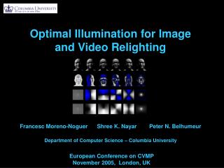
Video Relighting Using Infrared Illumintation. Oliver Wang and James Davis and Erika Chuang and Ian Rickard and Krystle de Mesa and Chirag Dave Department of Computer Science University of California, Santa Cruz EUROGRAPHICS 2008. Outline. Introduction.

E N D
Video Relighting Using Infrared Illumintation Oliver Wang and James Davis and Erika Chuang and Ian Rickard and Krystle de Mesa and Chirag Dave Department of Computer Science University of California, Santa Cruz EUROGRAPHICS 2008
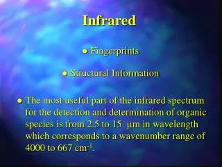
Introduction • Current technology trends will provide sufficient bandwidth to most home and office users within a few years. Looking forward to that point in time, what quality issues will remain? • Existing lighting setups in offices and homes have not been designed properly for photography, and there fore lead to poorly lit faces and distracting images. • Non-verbal communication, especially in the form of facial expressions, is thought to convey meaning more quickly than speech.[VP06] VUILLEUMIER P., POURTOIS G.: Distributed and interactive brain mechanisms during emotion face perception: Evidence from functional neuroimaging. Neuropsychologia 45 (2006), 174–194.
Introduction • Halo system, developed at HP, costs around $500,000. • We relight a video sequence using additional information acquired by an inexpensive, uncalibrated IR lighting setup.We chose to use IR lighting to compute an illumination basis as it is invisible to the human optical system and therefore can be placed in interactive environments without distracting the user. • The primary contribution of our work is a novel method for relighting faces • non-intrusive • compact enough for office desks • requires no user calibration • sufficiently simple for real-time implementation
Related Work Geometric Based Relighting Image Based Relighting Image Combinations Ratio Images
Related Work • Geometric Based Relighting • Using 3D model acquired by some kind of 3D scanner • These methods composite the rendered light from these geometric approximation with the original video • Difficulties • All require some kind of 3D geometry • Need 3D scanner, or assumed to be some preexisting model. • It is difficult to acquire accurate geometry from a purely image based approach, and for our purposes, it is unreasonable to require 3D head scans for each separate individual that we wish to relight. • If the precision of the model is reduced, alignment errors can cause artifacts when relighting the images, a problem complicated by non-rigid deformation in the face.
Related Work • Image Based Relighting • Debevec et al.[Acquiring the reflectance field of a human face00] introduced a complex gantry capable of capturing a dense basis space of images which were combined to produce new lighting condition. • This gantry was extended to very high frame rates for real time video applications [Performance relighting and reflectance transformation with time-multiplexed illumination05]. • Other work captured lighting information of objects, stored the information as polynomials and then interpolated between them to generate new images [Polynomial Texture Maps 01] .
Related Work • Image Based Relighting • Difficulties • Require complex capture setups that have to be precisely calibrated. • Using modulated lighting in the visible spectrum, which would be distracting for the user in a real time application.
Related Work • Image Combination • A different way to solve the lighting problem would be to combine separate parts from multiple images with varying lighting conditions to form one final image[Conveying shape and features with image-based relighting03][Interactive digital photomontage04]. • Difficulties • Rely on user annotation of the image. • Require roughly normalized lighting conditions across images to prevent visible seams.
Related Work • Ratio Images • The idea of using ratio images to encode the relation between two domains is not new. [Expressive expression mapping with ratio images01][Post-production Facial Performance Relighting using Reflectance07]
Research and Methods • Goal: • reduce the effects of harsh and uneven lighting and to correct for unnatural colored light cast by monitor glow • Methods: • capturing a series of IR images along with the original color video • Using this IR basis to compute a well lit IR image and then perform a retargeting into the visible domain
Image Acquisition • Two PointGrayDragonFly 2Camaeras • One is sensitive to IR and visible wavelengths • One is sensitive to just the visible specturm • Osram surface mount IR LEDs • Radiant intensity of 200mW/sr, 20.0ns rise and fall time, 940nm peak emission wavelength, and 60.0o half angle • Cold mirror as beam splitter • Reflects visible spectrum lightwhile passing light with a wave length longer than 780nm
Image Acquisition • Color camera runs at a rate of 15fps while our IR camera captures eight frames for each color frame, running at 120fps. • A subset of the images captured at each frame showing some IR lighting conditions and the color images
Image Acquisition • Because we cannot control the intensity of the room lighting, we must deal with the possibility of a low signal-to-noise ratio in our IR images. • We smooth image noise using a joint bilateral filter as described in Petschnigg et al.[Digital Photography with Flash and No-Flash Image Pairs04].
Image Acquisition • Bilateral filter: • p: pixels • A: ambient image • p’: others pixels in A • K(p) is a normalization term: • function gdsets the weight in spatial domain based on the distance between pixels • edge-stopping function gr sets the weight on the range based on intensity differences • both function are Gaussians with widths controlled by the standard deviation parameters and respectively • For 6 megapixel images, we set cover a pixel neighborhood of between 24 and 48 pixels. For images with pixel values normalized to [0.0, 1.0] we usually set to lie between 0.05 and 0.1, or 5 to 10% of the total range.
Image Acquisition • Joint bilateral filter • We observed the flash image contains a much better estimate of the true high-frequency information than the ambient image. Based on this observation, we modify the basic bilateral filter to compute the edge-stopping function grusing the flash image F instead of A . We call this technique the joint bilateral filter: • In practice, we have found that can be set to 0.1% of the total range of color values. • it can failin flash shadows and specularitiesbecause they only appear in the flash image, so we given mask M produced by our detection algorithm, our improved denoising algorithm becomes:
Image Acquisition • Joint bilateral filter • We use the color image to calculate the weights for the bilateral filter, which yields smooth results without blurring across edges.
Image Acquisition • We use a foreground mask to determine which parts of the image we use in computing the image weight. • We use similar to the technique shown in [Flash Matting06] : compute a rough foreground mask using the falloff of light. • We look at a difference between two IR images, one with all the lights on , and the other with all the lights off. Areas where the intensity change is greatest are assumed to be foreground.
Image Relighting • We compute a weight vector for the images using the equation: • A: a matrix with each column corresponding to an image in the basis space • : is the vector of image weight • Itarget: is the target image to solve for • We can create the new image using the following equation: • n: is the number of images in our basis • Ik: corresponds to the image under the kth lighting condition • wi: the ith image in the weight vector
Image Relighting • We can use any image Itarget and solve for an approximation of it as a combination of our bases. Given that we have poor lighting in the visible spectrum and arbitrary control over our IR illumination, a simple approach may be to just replace the poorly lit intensity channel with a well lit IR image. • However, this does not produce a satisfactory result as we are not used to seeing objects in the IR spectrum. • Skin and iris can appear lighter in IR, giving the IR image an unnatural ghostly appearance.
Image Relighting • We show how it would look if we just replaced the visible spectrum with information from the IR bases.
Spectral Consistency • Some objects are bright in IR and dark in the visible spectrum while other objects have opposite characteristics. ( X, Y ) = ( IR, Visible ) • However, this plot does not show the density of the points very well, it is hard to interpret this date.
Spectral Consistency • Therefore, we plot the same data but instead of looking at the relative intensities, we look at a histogram of the angle θ of each point in polar coordinates. • We can see the intensity was not the same in both spectral bands.
Spectral Consistency • We then plot the angle θ of the ratio of a pixel’s intensity between two scenes with the same viewpoint but different lighting directions in both the IR and visible spectrums. • Each point represents a pixel whose coordinates are: • We can see that in this plot,there is in fact a very strongcorrespondence, with mostpoints laying along the y=x,or 45o line.
IR Retargeting • Based on the results of our analysis, we would like to relight our scene not by substituting a well lit IR image directly into our final image, but by using it as an indicator of how much we want to change our visibly lit image. If an ideally lit IR image can be obtained from a poorly lit IR image by the equationIideal =(% change IR) * Iobserved. Then Section 3.3 indicates that a visible light image can also be corrected viaVideal (% change IR) * Vobserved. Combining these equations gives us the “ratio equation” : • In order to find Videal we must approximate both Iobserved and Iideal .
IR Retargeting • Iobserved: We do this by simply solving for a combination of IR bases that most closely matches Vobserved using the method described in Section3.2. • Iideal: We define Iideal to be the projection of a constant intensity image in the foreground face region into our IR bases.
IR Retargeting • The result of our algorithm on one frame of our video is shown in bottom. Notice that the intensity difference is greatly improved in the resulting image.
Chroma Correction • We can correct for this uneven chroma by applying our technique separately to the different color channels. We first determine a suitable face color heuristically by finding the median color in the face region. We can then solve for each color channel separately targeting the median face color in that channel. By adjusting color channels separately, we are actually changing the relative intensities in different wavelengths, which fixed the inconsistency in the color channels better than would be possible with simple color balancing.
Results • We implemented our algorithm in C++ using Intel’s OpenCV library. Using a Pentium 4 3.00 Ghz. machine, we were able to process frames at 13fps at 320x240 resolution.
Limitations and Future Work • Excessive movement between frames can cause artifacts, since the IR and color images are not in perfect temporal alignment. • Deep shadows or specular highlight contain very little color information and thus it is not possible to accurately correct the light intensity in these regions. • Replace the standard RGB Bayer pattern in a camera with one that includes an IR sensitive color channel in addition to RGB. • IR light and a single modified camera are built into a monitor frame for a cost approximately the same as current implementation. • It is also possible to adaptively change the IR bases so that fewer images need to be captured per frame. This could relax the need for a high speed camera as well as reduce errors from temporal misalignment.
Conclusion • We have introduced a system that is inexpensive, compact, and non-invasive. With our method, we are able to fix much of the poor lighting that noticeably degrades typical video conferencing. • Our setup is uncalibrated and robust, the light bars can be positioned by hand and even moved during capture.