Download

1 / 126
2.12k likes | 3.48k Views
Study Guide. 1998 Cessna 172 S. For Training Use Only Obtain actual weights, c.g, fluid capacities and dimensions from the Pilot Operating Handbook for your actual Training airplane.

E N D
Study Guide 1998 Cessna 172 S For Training Use Only Obtain actual weights, c.g, fluid capacities and dimensions from the Pilot Operating Handbook for your actual Training airplane.
This presentation is based on the POH for the 1998 Cessna 172 S, and covers the following sections of that manual. Section 1 General Section 2 Limitations Section 3 Emergency Procedures Section 4 Normal Procedures
Section 1 Descriptive Data
Aircraft Dimensions Length 27’ 2” Height 8’ 11” Wingspan 36’ 1” Wing Area of 174 square feet
Engine Manufactured by Textron Lycoming Model O-360-L2A This is a Normally Aspirated, Direct Drive, Air-Cooled, Horizontally-Opposed , Fuel Injected, Four Cylinder Engine with 360 cubic inches displacement. 180 BHP @ 2700 RPM
Propeller Manufactured by McCauley Model 1A170E/JHA7660 Two Bladed, Fixed Pitch, Aluminum. Diameter is 76”
Fuel Approved Fuel Grades: 100LL Grade Aviation Fuel (BLUE) 100 Grade Aviation Fuel (GREEN) • This is a 152, you will have 13 drains to check
Fuel • 2 integral tanks [one in each wing] hold the fuel • The Un-usable fuel includes fuel in the feed lines within the wing struts, Fuel Reservoir, and associated plumbing • The System is Gravity Feed, and uses an Electric Auxiliary Fuel Pump for priming the Fuel Injection system • There are 13 Fuel Drains • 5 below each wing tank • 3 below the nose • These drains should be tested for water and contamination prior to flight
Fuel • This aircraft is equipped with a Fuel Selector Valve that allows Fuel to flow from Left, Right, or Both Fuel tanks. BOTH is the Normal selection. • A FUEL SHUT-OFF is also installed in this aircraft for use in Emergency Procedures, or for prolonged Storage.
Fuel • Total Capacity 56 gallons • Total Useable 53 gallons • Total Each Tank 28 gallons • Total Useable 26.5 gallons • Non-Useable 3 gallons
OIL • Grade appropriate to temperature ranges • Often this is 15w50 or 20w50 • Check Maintenance Records for actual type used in your aircraft.
Electrical System • System is 28 Volt DC • Powered by a belt driven 60 amp alternator • Supplying a 24 Volt Battery • Battery is located forward of Firewall, Left Side • Current is supplied Through Split Primary Bus Bars 1 and 2 • Essential Bus is wired between the 2 primaries to energize Master, • …..Annunciator, and Interior Lighting • Each Primary is connected to an Avionics Bus by the Avionics Master • Continued…………….
Electrical SystemContinued • Master Switch is a Split Rocker type switch labeled MASTER • On is in the up Position, Off is in the Down Position • The Right Half is labeled BAT and connects Battery Power to Buses • The Left Half is labeled ALT, connects the Alternator • Normally, BAT and ALT are used simultaneously • BAT can be turned on to check electrical equipment on the ground • When the ALT switch is OFF the entire system runs on battery
Electrical SystemContinued • LOW VOLTAGE Annunciator, Will Illuminate when Voltage falls below 24.5 Volts • OVERVOLTAGE :Alternator Control Unit automatically opens the ALT FLD circuit breaker, Shutting Off the Alternator • Under these conditions, with normal power use, a low voltage condition will occur eventually, and the Low Volt annunciator will illuminate • The Alternator Control unit may be then reset by resetting the ALT FLD circuit breaker • If this occurs a second time, terminate the flight
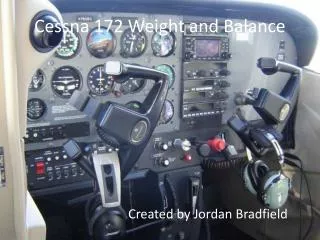
Maximum Certificated Weights • Ramp Weight Normal Category 2558 • Ramp Weight Utility Category 2208 • Takeoff Weight Normal Category 2250 • Takeoff Weight Utility Category 2200 • Landing Weight Normal Category 2550 • Landing Weight Utility Category 2200
Baggage Compartment Weights • Normal Category • Area 1 120 lbs • Area 2 50 lbs • Maximum Combined Area 1 and 2 120 lbs
Baggage Compartment Weights • Utility Category • In this Category the Rear Seat must be un-occupied, and the baggage compartment must be empty.
Standard Airplane Weights • Standard Empty Weight 1663 • Normal Category Useful load 895 • Utility Category Useful Load 545
Specific Loadings • Wing Loading: 14.7 lbs./sq. ft. • Power Loading: 14.2 lbs./sq. ft.
Baggage Compartment Weights Relate to Category • Normal Category • Area 1 120 lbs • Area 2 50 lbs • Maximum Combined Area 1 and 2 120 lbs • Utility Category • All Baggage areas must be empty
Section 2 Limitations
Airspeed Limitations VNE [ Red Line ] Never Exceed 163 Do not exceed this speed.
Airspeed Limitations VNO [Upper Limit of Green Arc ] Maximum Structural Cruise 129 Exceed only in smooth air.
Airspeed Limitations VA Maneuvering Speed Based on weight. The less weight, the slower the speed. 105 @ 2550 lbs 98 @ 2200 lbs 90 @ 1900 lbs
Airspeed Limitations Flap Extension
Airspeed Limitations VFE Flap Extension Speeds Do not exceed with Flaps Down 10 degrees 110 20 degrees 85 30 degrees 85
Airspeed Limitations Max window open speed 163 Do not exceed with window open
Airspeed Indicator Markings White Arc 40 - 85 Flap Operating Range Lower limit is max weight Vso [Stall Speed Flaps Landing Configuration] Upper limit is Vno [max speed flaps extended]
Airspeed Indicator Markings Green Arc 48 - 129 Normal Operating Range Lower limit is max weight Vs [Stall Speed No Flaps ] Upper limit is max structural Cruise, or Vno
Airspeed Indicator Markings Yellow Arc 129 - 163 Caution Range Operation with caution only in smooth air.
Airspeed Indicator Markings Red Line 163 Maximum Speed for all operations Fly Faster than this speed, and you are a Test Pilot !
Power Plant Limitations Maximum Power 180 BHP
Power Plant Limitations Engine Operating Limits for Takeoff and Continuous Operations Maximum Engine Speed 2700 RPM Red Line
Power Plant Limitations Static RPM Range at Full Throttle Static RPM range 2300-2400
Power Plant Limitations Maximum Oil Temperature 245 degrees (f) or 118 (c)
Power Plant Limitations Oil Pressure 20 PSI Minimum 115 PSI Maximum
Power Plant Limitations Oil Grade Aviation Grade Straight Mineral Oil or, Ashless Dispersant Oil
Power Plant Limitations • Engine Oil : • 15w50 or 20w50 • Check Maintenance Records for actual type used in your aircraft.
Power Plant Instrument Markings Tachometer Red Line 2700 RPM
Power Plant Instrument Markings Oil Temperature Green Arc 100-245 Red line 245
Power Plant Instrument Markings Oil Pressure Red Line Minimum 20 PSI Green Arc 50 – 90 PSI Red Line Maximum 115 PSI
Power Plant Instrument Markings Fuel Quantity Red Line 0 1.5 Gallons Unusable Each Tank
Power Plant Instrument Markings Fuel Flow 0 to 12 GPH
Power Plant Instrument Markings Vacuum Gage 4.5 to 5.5 PSI