Download
1 / 30
300 likes | 459 Views
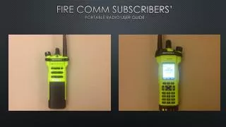
P5130 Portable Radio User’s Guide for York County, PA Emergency Services. Training Session Notes. *SAFETY ITEMS*.

E N D
P5130 Portable Radio User’s Guide forYork County, PA Emergency Services Training Session Notes
*SAFETY ITEMS* • DO NOT...operate the portable radio near or in an area where blasting is taking place. Anyone using radio controlled explosives must post signs. If you see a caution sign about blasting in the area, you must turn your radio off. This applies to any radio equipment capable of transmitting: phones, CB’s, etc. • DO NOT...operate the portable radio in an explosive atmosphere. The radio is an electrical device with switches that can cause an explosion in an explosive atmosphere. If you can operate your vehicle or any power tools, it is safe to use the radio.
DO NOT operate the radio without a proper antenna. DO NOT transmit for more than 50% of the total radio use. Always use only Tyco Electronics authorized accessories. Always keep the antenna at least 5cm (2 inches) away from the body while transmitting. *SAFETY ITEMS* • To ensure that user exposure to RF electromagnetic energy is within the FCC allowable limits for occupational use, always adhere to the following guidelines:
It is a violation of FCC rules to interrupt any distress or emergency message. Any use of profane or obscene language is prohibited. It is against the law to send false call letters or a false distress or emergency message. All messages must be brief and limited to the business need. It is a violation of FCC rules to send personal messages, unless in an emergency. The FCC requires that radio systems be identified by use of the assigned Call Letters. The radio system does this automatically. Operating Rules and Regulations • The Federal Communications Commission sets all rules for two-way radio use. The user of two-way radio equipment should be familiar with these basic rule requirements.
Project 25 (P25) • Project 25 is a public safety communications standard dedicated to ensuring interoperability in communications. It is designed to ensure fast and secure communications between local, state and federal agencies when protecting the public's welfare. • The Project 25 standard organization is comprised of the Association of Public Safety Communications Officials (APCO), the National Association of State Telecommunications Directors (NASTD) and the U.S. Federal Government. • The Federal Government through the National Telecommunications and Information Administration (NTIA) has dictated that all new and existing federal communications systems will be P25 compliant. • P25 is an all digital voice system that can be trunking or conventional non-trunking.
Group B Group D Group D Conventional vs. Trunked Trunked Approach Conventional Approach Channel 1 Channel 2 Group C Group A Group C Group A Group B Users Select which Repeater to Use System Selects which Repeater to Use
Why Trunking? • Trunking: • Improves spectral efficiency • Relieves the user from managing the channel • Encourages cross agency / shared communications • Establishes communications privacy • Encourages private communications • Discourages eavesdropping by scanners • Establishes “queuing” rather than “waiting” • Enables priority use during busy times
P25 Trunking System Features • Digital Control Channel • Multiple Working Channels • < 0.5 Second Access • Group & Individual Voice Calls • Unit ID for each radio • Late / Delayed Entry • Emergency Calls • Queuing with Priority • Unit Enable / Disable • Wide Area Coverage
How Far Does it Cover ? • Many factors affect range: • Site Location • Urban Clutter • Reflections / Multipath • Ducting over Water • Heavy vegetation • Weather • Frequency ???
Simulcast – Extending the Coverage • SIMULtaneous broadCAST • All RF sites have: • Same number of channels • Same radio frequencies • Same channel designated as control channel • When someone makes a call, that call is rebroadcast to every site regardless of whether or not someone is there to listen. • The users have no indication that simulcasting is occurring other than better coverage.
Multisite – Extending Coverage • Units inform the network of their location: • Each time the Radio is powered up. • Each time a System selection is made. • Each time a Group selection is made. • When Radio detects a high bit error rate on the Control Channel • Radio will look for another site using an algorithm. • Automatically switches to new site when criteria is met. RF Site 2 RF Site 1
Radio Nomenclature • Before actually operating the radio, one should know some of the terms and descriptions associated with operation. Such as: • Buttons • Knobs • Antenna • Microphone • Speaker • Display • Battery • Let’s take a look at these before actually operating the radio.
P5130 (Select) Views Default Designations Of Controls System/Group/ Channel Knob Antenna Universal Device Connector “UDC” (On Side) Display Microphone Speaker
LCD Display • The display has 3 lines. • Lines 1 & 2 contain eight alphanumeric characters. • Line 3 uses 10 groups of pixels to show radio status icons. • All three lines are used in menu mode.
LINE 1: System Name (example: CENTRAL) Volume Level (VOL = 10) Caller Identification (GR 1234) Low Battery (LOW BATT) ‘Who Has Called’ (* WHC *) LINE 2: Talkgroup or Channel Name (EMS MAIN) Call Queued (QUEUED) System Busy (SYS BUSY) Call Denied (DENIED) Individual Call (*INDV*) Control Channel Scan (CC SCAN) Wide Area Scan (WA SCAN) Receive Emergency (*RXEMER*) Transmit Emergency (*TXEMER*) Display Messages • Listing of messages that appear on line 1 and 2.
Encrypted Digital Speech Special call select/entry mode (Individual or Telephone) Transmit Failsoft Low battery ON transmitting or receiving FLASHING call queued Selected group in scan list Selected group is priority-two scan Conventional Channel Guard Digital P25 Analog ON - low TX power OFF - high TX power Selected group is priority-one scan SCAN enabled (rotates clockwise) Line 3 Icons • An icon will be displayed to show radio status.
Antenna • Firmly screw in the provided antenna with your hand. • The antenna is designed and possibly trimmed for your frequency of operation. • Do not use any other antennas without approval. • Use of unapproved antennas will affect system performance and possibly cause failure of the radio. • If the antenna becomes cracked, broken or bent, replace it.
1 3 2 Install or Change the Battery • Before changing the battery, turn the radio off. • Press up on the battery release button on the bottom of the battery. • Lift the bottom of the battery pack up and away until it separates from the radio. • Insert the top of the new battery pack onto the radio then push down the bottom of the battery pack until it clicks. When the belt clip is installed, one will need to press the belt clip to relieve pressure from the battery to remove it.
CENTRAL EMS MAIN Basic Operation • Items to Discuss • Power on the radio. • Read the display. • Change systems. • Change groups. • Originate a group call. • Receive a group call. • Declaring an Emergency.
Power On and Log In • Rotate Volume On/Off Control Clockwise about ¼ turn. • All segments of the LCD display should briefly display and the display should show Power Up Self Test, followed by an audible beep and the system/group display. • The radio will transmit into the network and log in automatically, telling the network the ID of the radio and the group that is selected. Power On/Off & Volume CENTRAL EMS MAIN
Displaying the Systems and Groups • The radio’s display is showing the system and group that you are part of. • The top line will be the system name representing a location and a set of groups. Examples are: • NORTH • WEST • CENTRAL • SOUTH • FULTON • UTAC • The second line will show the selected group control by the small buttons on the side of the radio. Examples are: • MAIN • CF ADMIN • CAR CAR1 • EMS MAIN • UCALL 40 • etc
CENTRAL EMS MAIN Originate a Group Call • Turn on the radio. • Select the group you want to talk to. • Group names appear on Line 2 of the display. • Push-to-Talk (PTT). • Indicator will light red while transmitting • Speak into the microphone. 1 5 2 3 4 6
CENTRAL EMS MAIN Changing Groups • The Group name will appear on Line 2 of the display. • Press the upper side button to ramp up to the desired group. • Press the middle side button to ramp down to the desired group. 2 1 3 There are lots of groups to ramp through!
CENTRAL EMS MAIN Changing the System • Use the top knob to select the system. • System names appear on Line 1 of the display. • The groups are the same in all of your systems. The System represents a location and a set of groups. 1 2 In normal operation, the system name may change as the radio acquires the best RF site for operation. The radio will not select the FULTON or UTAC system automatically.
GR 12345 EMS MAIN Receiving A Group Call • The caller’s Radio ID or alias appears on Line 1 (ex. 12345). • The group that is being received appears on Line 2. • The Indicator will light green while receiving. • Adjust Power On/Off & Volume control for pleasing level of audio, but not to overdrive the speaker. • PTT to respond. 4 3 1 2 5
CENTRAL *TXEMER* Declaring an Emergency • Press and hold the red EMERGENCY button for approximately 2.2 seconds. • *TXEMER* appears in display and will continue to flash, alternating with the selected group, until the emergency is cleared. • PTT Top View 1 1 3 2 Receive Indication EM 12345 *RXEMER* • The console dispatcher clears emergencies. • If you declare an emergency, your radio will remain on the group until the emergency is cleared.
Accessories • Speaker Microphones - General • External Antenna • Radio Antenna • Holders • Belt Clip • Belt Loops • Leather Case • Fabric Case
Battery Information • P5100 Series Radios Rated Battery Life (at 5% Tx, 5% Rx, and 90% standby): NiCd: 8 hours (1600 mAH) NiMH: 11 hours (2400 mAH) • Battery Charging Indications (Typical charger) Slow Red Flash – PreCharge (10 minutes max) Extremely Discharged Cold battery Solid Red – Charging ~ 1 Hour NiCd ~ 2 Hours NiMH Solid Green – Ready / Trickle Charge Red / Green Flash – Battery temp too hot Remove and let cool before attempting to charge Fast Red Flash – Error Remove and Reinsert
M/A-COM, Inc. Technical Training Center Telephone 434-455-9469 www.macom-wireless.com Copyright© 2008 M/A-COM, Inc. All rights reserved.