Download
1 / 24
500 likes | 1.43k Views
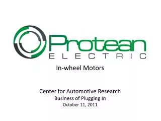
Wheel Hub Motors for Automotive Applications. EVS-21 April 5, 2005 James Nagashima General Motors Advanced Technology Center. Concept Development. Wheel Motors were developed for the Autonomy fuel cell concept vehicle project.

E N D
Wheel Hub Motors for Automotive Applications EVS-21 April 5, 2005 James Nagashima General Motors Advanced Technology Center
Concept Development • Wheel Motors were developed for the Autonomy fuel cell concept vehicle project. • Enables the low profile “skateboard” chassis by placing the traction motors in the wheels. • Allows more chassis space for Fuel Cell components.
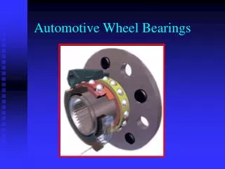
What is a Wheel Hub Motor ? • High torque, permanent magnet electric motor • Completely contained within the wheel • Low Speed, 1,200 RPM • Direct drive, no gears • Integrated with wheel bearing and hub
Advantages of Wheel Motors • Eliminates drivetrain losses, harmonics and gear backlash • No gears – extremely quiet • Electric motor can compensate for gear-shift torque disturbances from ICE to enhance driver comfort • Provides lots of low-end torque • Enables higher level of vehicle control flexibility • Natural tie-in to AWD and stability control • Capability to control torque at each wheel independently and selectively • More even mass distribution for better handling and driver comfort • Universally applicable to anything with wheels
Current Flux Torque Magnets Rotor 2 Rotor 1 Stator Motor Operating Principle • Surface PM Axial Flux machine • 2 outer Rotors with NdFeB magnets and 1 central Stator. • Magnetic flux crosses stator air-gap parallel to axis of rotation. • Current flows radially in stator coils wound around laminated core. • Lorenz force is created as cross product of current & flux, creating torque around axis of rotation.
Coreless design Stator windings fixed in epoxy with non-magnetic coolant tube in center Lower overall mass due to epoxy core Large air-gap = Large magnet mass Low inductance = Small flux weakening range Magnetic Core vs. Coreless Designs Slotted core design • Stator wires wound around laminated magnetic core. • Higher overall mass due to iron core. • Small air-gap = Low magnet mass. • High inductance = Large flux weakening range
Wheel Motor Requirements • Two wheel motors are mounted on the rear axle to supplement the front traction system. They provide 60% additional torque to the existing S-10 electric truck.
Motor Design Parameters • Motor designed to fit within 17” wheel • Used modified wheel bearing and hub from Buick Rendezvous • Electrical parameters to match existing GM power inverter. • Liquid cooling using separate pump and radiator
Power Leads Resolver Leads Hub Coolant Connections Machine Fabrication and Tests • Motor was jointly designed between University of Rome and GMATC Torrance. • All motors built at Lucchi Elettromeccanica, Italy. • Initial testing in Rome • Generator operation, back EMF, thermal, low power. • Dynamometer testing at ATC • Controls development • Thermal, full torque, power, efficiency, spin loss, etc. Wheel Motor in Assembly at Lucchi Finished Wheel Motor on the bench
Torque, Measured vs. Predicted • 500 Nm torque range exceeded specification. • At 350 VDC full torque to top speed.
Power, Measured vs. Predicted • Peak power (30 sec rating) exceeded spec.
Magnetic Wedges Reduce Losses • Soft magnetic composite wedges were inserted into slot openings which greatly reduced slot harmonic losses.
System Efficiency (Inverter + Motor) • Overall system efficiency in the mid-80% range in both motoring and regeneration. Motoring @ 350VDC Regeneration @ 350VDC
Test Vehicle Construction • Started with existing electric S-10 Truck with 100 kW front electric motor and 320 V battery pack. • Two 25 kW , 500 Nm wheel hub motors added to rear axle. • Vehicle modifications were done at Quantum Technologies facilities.
Chassis Modifications • Two 70 kW inverters and radiators are mounted underneath the vehicle behind the rear axle. • Coolant fill and reservoir for rear traction system mounted on side of bed. Identical systems on left and right hand sides.
Suspension Modifications • Axle length shortened to maintain correct rear track • Wheel Motors bolted to modified flange on solid axle.
InteriorModifications • Added controls mounted between the driver and passenger. PC laptop mounting provided here. Operator can choose front/rear/both traction systems. • Data Acquisition System installed to monitor key parameters.
Media Event • Event held at Irwindale Raceway August 2003 • Press briefing by Dr. Lawrence Burns, GM R&D. • Drag racing against 4 & 6 cylinder S-10 trucks. • Wheel motors provided 60% more torque. • Wheel motors outperformed competitors in ¼ mile drag.
Showcase of GM automotive technology Los Angeles, San Francisco, Tokyo, Beijing Test drives for Press, Government Officials, Celebrities, and Public >1,000 drivers, extreme weather. No motor problems Everyone loved the brisk acceleration. GM Tech Tours
Applies to ICE, Electric, and Fuel Cell vehicles. 2WD or 4WD applications Easily added to FWD or RWD platforms Creates on-demand AWD Hybrid Enhanced vehicle stability controls not possible with mechanical traction. Potential Applications
Advanced 4 wheel steering. Mechanical steering or torque steering. Could enhance lane keeping, collision avoidance, and advanced stability controls Permits zero turning radius in 4WD. Gets out of tight parking spaces. Auto-Park controls. More Applications
Next Generation • Next Generation of Wheel Hub Motors are featured on “Sequel” FC Concept Vehicle.
Conclusions • Presented design and development of an axial flux PM, direct drive wheel hub motor. • Measured performance exceeded requirements. • Demonstration vehicle shown to public at media event and GM Tech Tours in 2003 • Next Generation motor shown on Sequel FC vehicle in 2005. • Unique features make them desirable for future applications.
Acknowledgments • Dr. Khwaja Rahman, GM Powertrain • Professor Fabio Crescimbini, University Roma Tre • Professor Federico Caricchi, University of Rome “La Sapienza” • Dr. Giorgio Lucchi, Lucchi Elettromeccanica • Quantum Technologies, Irvine CA • GM Advanced Technology Center Team