Download
1 / 1
10 likes | 167 Views
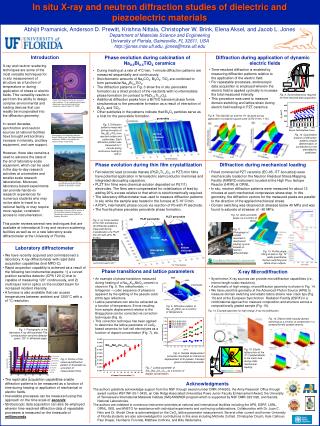
In situ X-ray and neutron diffraction studies of dielectric and piezoelectric materials. 2 θ. ω. Acquisition Electronics. Function Generator. Amplifier or HV switch. PC. (00 h ). cubic. orthorhombic.

E N D
In situ X-ray and neutron diffraction studies of dielectric and piezoelectric materials 2θ ω Acquisition Electronics Function Generator Amplifier or HV switch PC (00h) cubic orthorhombic Abhijit Pramanick, Anderson D. Prewitt, Krishna Nittala, Christopher W. Brink, Elena Aksel, and Jacob L. Jones Department of Materials Science and Engineering University of Florida, Gainesville, FL 32611, USA http://jjones.mse.ufl.edu, jjones@mse.ufl.edu Tetragonal G. L. Brennecka, B. A. Tuttle, Journal of Materials Research2007, 22, 2868. Introduction • Phase evolution during calcination of Na0.5Bi0.5TiO3 ceramics • During heating at a rate of 4°C/min, 1-minute diffraction patterns are measured sequentially and continuously. • Stoichiometric amounts of Na2CO3, Bi2O3, TiO2 are combined to form perovskite Na0.5Bi0.5TiO3. • The diffraction patterns in Fig. 3 show the in situ perovskite formation as a direct product of the reactants with no intermediate phase formation (in contrast to PbZr0.5Ti0.5O3). • Additional diffraction peaks from a Bi/Ti/O transient phase forms simultaneous to the perovskite formation as a result of interaction of Bi2O3 and TiO2. • Other subtleties in the patterns indicate that Bi2O3 particles serve as a host for the perovskite formation. Diffraction during application of dynamic electric fields • Time-resolved diffraction is enabled by measuring diffraction patterns relative to the application of the electric field. • For repeatable processes, stroboscopic data acquisition is employed wherein the electric field is applied cyclically to increasethe total measured intensity. • This procedure was used to measure domain switching and lattice strain during electric field loading in PZT ceramics. X-ray and neutron scattering techniques are some of the most versatile techniques for in situ measurement of structure as a function of temperature or during application of stress or electric fields. This versatility results in part from the ability to design complex environmental and loading devices that can readily be incorporated into the diffraction geometry. In recent decades, synchrotron and neutron sources at national facilities have brought extraordinary increase in intensity, ancillary equipment, and user support. However, there also remains a need to advance the state of the art of laboratory-scale equipment, which can be used in the day-to-day research activities at universities and smaller scale research laboratories. Moreover, laboratory-based experiments can provide hands-on research experiences for numerous students who may not be able to travel to a national facility or may require more regular, consistent access to instrumentation. Fig. 8. Some electronics required for time-resolved data acquisition. Image from Argonne National Laboratory press release, “X-ray scattering techniques determine how dissolved metal ions interact in solution” (April 12, 2007). Fig. 9. The 002/200 (a) and the 111 (b) peak during application of a bipolar square wave (±750 V/mm, 1 Hz). perovskite Fig. 3. Diffraction patterns measured during formation of Na0.5Bi0.5TiO3 from reactant oxides and carbonates. Each diffraction pattern was measured for 1 minute during continuous heating to 700°C. Bi/Ti/O transient phase Fig. 10. Quantitative analysis of diffraction patterns enable determination of contributions to the piezoelectric coefficient. Photograph of the Spallation Neutron Source (SNS) at the Oak Ridge National Laboratory (ORNL), the highest flux neutron source in the world. Mix of Na2CO3, TiO2, and Bi2O3 • Phase evolution during thin film crystallization • Ferroelectric lead zirconatetitanate (PbZrxTi1-xO3, or PZT) thin films have potential application in ferroelectric semiconductor memories and integrated decoupling capacitors. • PLZT thin films were chemical-solution deposited on Pt(111) electrodes. The films were compensated for volatilization of lead by adding 20% excess relative to that which is stoichiometrically required. • The laboratory diffractometer was used to measure diffraction patterns in situ while the sample was heated in the furnace at 5-10°C/min. • A PbPtxintermetallic phase occurs via reaction of Pb with Pt electrode. • The fluorite phase precedes perovskite phase formation. • Diffraction during mechanical loading • Poled commercial PZT ceramics (EC-65, ITT Acoustics) were mechanically loaded on the Neutron Residual Stress Mapping Facility (NRSF2) instrument, located at the High Flux Isotope Reactor (HFIR) at ORNL. • In situ, neutron diffraction patterns were measured for about 12 minutes at each mechanical compressive stress step. In this geometry, the diffraction vectors for the measured peaks are parallel to the direction of the applied mechanical stress. • Domain switching was observed at stresses below 40 MPa and was found to saturate at stresses of ~80 MPa. Photograph of the European Synchrotron Radiation Facility (ESRF) in Grenoble, France. Photograph of the new OPAL reactor at the Australian Nuclear Science and Technology Organisation (ANSTO) in Sydney, Australia. Fig. 12. (002) and (200) peaks as a function of stress. PLZT perovskite PLZT perovskite (b) Fig. 4. (a) Cross section of thin film architecture; (b) Diffraction patterns measured during crystallization of a PLZT thin film with 20% Pb excess. This poster reviews several new techniques that are available at international X-ray and neutron scattering facilities as well as on a new laboratory-scale diffractometer at the University of Florida. Fig. 11. Photograph of sample mounted in mechanical loading rig and located on neutron diffractometer. Fluorite PbPtx (a) Pt bottom electrode • Laboratory diffractometer • We have recently acquired and commissioned a laboratory X-ray diffractometer with rapid data acquisition capabilities (Inel MPD-C). • Rapid acquisition capability is achieved as a result of the following two instrumental aspects: 1) a curved position sensitive detector (CPS 120-C) that is capable of measuring 120° continuously, and 2) multi-layer mirror optics on the incident beam for increased incident intensity. • A furnace is also available that can access temperatures between ambient and 1200°C with a ±1°C resolution. • The rapid data acquisition capabilities enable diffraction patterns to be measured as a function of time during heating or application of mechanical or electric fields. • Irreversible processes can be measured using this approach on the time scale of seconds. • Stroboscopic data acquisition can also be employed wherein time-resolved diffraction data of repeatable processes is measured on the timescale of milliseconds. Amorphous film Fig. 13. Profile shape fitting of data in Fig. 12 yields quantitative domain switching and lattice strain outputs. Phase transitions and lattice parameters • An example of phase transitions measured during heating of a Na0.5K0.5NbO3 ceramic is shown in Fig. 5. The orthorhombic → tetragonal → cubic sequence of phases is apparent by the splitting of the pseudo-cubic (00h)-type reflections. • Lattice parameters can also be extracted as a function of temperature. Errors resulting from sample displacement relative to the Bragg plane can be corrected via correction techniques (Fig. 6). • This correction technique has been applied to determine the lattice parameter of CeO2-based ceramics for fuel cell electrolytes as a function of dopant concentration (Fig. 7), etc. • X-ray Microdiffraction • Synchrotron X-ray sources can provide microdiffraction capabilities (i.e., micron length scale resolution). • A schematic of high-energy, microdiffraction geometry is shown in Fig. 14. • We have used this geometry at the Advanced Photon Source (APS) to measure domain switching and elastic lattice strains near crack tips (Fig. 15) and at the European Synchrotron Radiation Facility (ESRF) in a combinatorial approach to measure composition and structure across a compositionally graded sample (Fig. 16). Fig. 5. Diffraction pattern of Na0.5K0.5NbO3 as a function of temperature. Fig. 14. Example geometry for high-energy X-ray microdiffraction. 15 minutes 5 minutes Fig. 16. Electric-field-induced domain switching as a function of composition in a compositionally graded ceramic. 100 seconds 60 seconds 30 seconds 10 seconds 3 seconds Fig. 1. Photographs of the laboratory X-ray diffractometer The curved position sensitive detector spans 120° in diffracted angle. 1 second Fig. 15. Elastic lattice strain of the (111) perpendicular to the crack face during static mechanical loading. Fig. 6. Sample displacement correction illustrated for intentional displacement of Si powder. Intercept gives true lattice parameter. Fig. 2. Portion of the measured diffraction pattern of Si powder as a function of measurement time. Fig. 7. Lattice parameter of Smx/2Ndx/2Ce1-xO2- δ as a function of dopant concentration. The authors gratefully acknowledge support from the NSF through award number DMR-0746902, the Army Research Office through award number W911NF-09-1-0435, an Oak Ridge Associated Universities Powe Junior Faculty Enhancement Award, the University of Tennessee’s International Materials Institute (IMI) ANSWER program which is supported by NSF DMR-0231320, and Sandia National Laboratories. The authors are indebted to numerous instrument scientists at national and international facilities including the APS, ESRF, LANL, ORNL, ISIS, and ANSTO for assistance with individual experiments and continuing collaborations. Collaboration with Dr. Juan C. Nino and Dr. Shobit Omar is acknowledged on the CeO2 lattice parameter measurement. Several other current and former University of Florida students are also acknowledged for contributions in this area including Michelle Cottrell, Christopher Dosch, Kyle Calhoun, Paul Draper, Humberto Foronda, Matthew Cothrine, and Billy Valderrama. Acknowledgments