Download
1 / 46
540 likes | 2.8k Views
JET PROPULSION. Part 5 Jet Engine Operation Oil, Fuel & Ignition Systems. Introduction. Viscosity is the resistance of a fluid to flow. (All fluids exhibit viscosity to some degree) Low Viscosity means the liquid is not very thick, and flows easily. High Viscosity

E N D
JET PROPULSION Part 5 Jet Engine Operation Oil, Fuel & Ignition Systems
Introduction Viscosityis the resistance of a fluid to flow. (All fluids exhibit viscosity to some degree) Low Viscosity means the liquid is not very thick, and flows easily. High Viscosity means the liquid flows much slower because it’s thicker. Honey is a high viscous fluid when cold, but hot honey has a much lower viscosity. The same applies to oil.
The Oil System OIL COOLER OIL PUMP ASSEMBLY OIL TANK Location bearings support the engine rotor. The purpose of the oil system is • to provide lubrication to the shaft bearing chambers • and to remove friction generated heat. • Oil is sucked out of the tank by a pressure pump, • through an oil cooler, PUMP to the bearing chambers.
Dry Sump Recirculating System Scavenge Pump SUMP Early jet engines were a total loss system Engine Bearing Chamber Pump Cooler Oil Tank Scavenge pumps take all the oil out of the sump, hence the term ‘DRY-SUMP’, and replace it in the tank – hence the term ‘DRY-SUMP RECIRCULATING’. Modern jet engines have mostly Dry Sump systems. i.e. oil was lost in the gas stream
Dry Sump Recirculating System OIL COOLER OIL PUMP ASSEMBLY SCAVENGE OIL TANK Each chamber is scavenged by its own pump, to a single return flow back into the oil tank. If metal bearings disintegrate they create particles, so magnets are fitted into the system called Magnetic Chip Detectors (MCD’s). MCD MCD MCD PUMP MASTER MCD
The Bearing Oil Supply Let’s take a closer look at what happens here.
The Bearing Oil Supply Pressurised air from compressors Oil Jet Scavenge Oil to tank High pressure air forced into the Bearing Chamber prevents oil loss Shaft Shaft • Oil is delivered by direct jet and centrifugal distribution. • It then drops down to be taken by the scavenge pumps. To prevent oil loss, the chambers need to be sealed. • As the bearings are situated between • rotating and static parts of the engine, • Air Supported Sealing Vents are added. Oil Supply
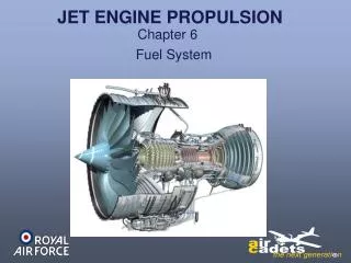
Fuel Systems Broadly speaking there are four main categories of aviation fuel used in the RAF and RN: AVGAS, AVTUR, AVTAG and AVCAT and broadly speaking there are two main fuel systems used in jet engines: HYDRO-MECHANICAL and ELECTRONICALLY CONTROLLED
MECHANICAL DRIVE FROM ENGINE OIL IN BOOSTER PUMP Fuel Systems Hydro-Mechanical Systems FUEL/OIL HEAT EXCHANGER LP FUEL PUMP OIL OUT WING FUEL TANK LP FUEL FILTER Fuel from the Wing Tanks, is pumped by Booster to the engines. • The Low Pressure Fuel Pump • is driven mechanically by the engine. • The Fuel/Oil Heat Exchanger • transfers heat from the hot oil to the cold fuel. • The Low Pressure Fuel Filter • ensures the fuel is free of contaminants.
MECHANICAL DRIVE FROM ENGINE OIL IN BOOSTER PUMP PUMP OUTPUT CONTROL SIGNAL Fuel Systems Hydro-Mechanical Systems FUEL/OIL HEAT EXCHANGER LP FUEL PUMP OIL OUT WING FUEL TANK HP FUEL PUMP LP FUEL FILTER The High Pressure Fuel Pump, driven mechanically by the engine, is a Positive Displacement Pump, so flow is relative to pump speed, and if the pump stops - the fuel will stop. The Fuel Control Unit (FCU) controls the HP fuel pump, by a metered fuel pressure signal. FUEL CONTROL UNIT
MECHANICAL DRIVE FROM ENGINE OIL IN BOOSTER PUMP PUMP OUTPUT CONTROL SIGNAL Fuel Systems Hydro-Mechanical Systems FUEL/OIL HEAT EXCHANGER LP FUEL PUMP OIL OUT FUEL DISTRIBUTION AND SPRAY NOZZLES WING FUEL TANK HP FUEL PUMP LP FUEL FILTER FUEL CONTROL UNIT Finally, the HP fuel pump delivers the fuel, at high pressure, to the Fuel Spray Nozzles.
MECHANICAL DRIVE FROM ENGINE OIL IN BOOSTER PUMP FADEC ELECTRONIC SIGNAL FUEL SPILL FLOW PUMP OUTPUT CONTROL SIGNAL Electronically Controlled Systems LP FUEL PUMP FUEL/OIL HEAT EXCHANGER HP FUEL PUMP OIL OUT FUEL DISTRIBUTION AND SPRAY NOZZLES WING FUEL TANK LP FUEL FILTER FUEL CONTROL UNIT FUEL METERING UNIT Electronic systems have LP & HP pumps in one unit, and a Fuel Metering Unit tocontrol the engine speed via the throttle valve and the fuel spill valve.
MECHANICAL DRIVE FROM ENGINE OIL IN BOOSTER PUMP FADEC ELECTRONIC SIGNAL FUEL SPILL FLOW Electronically Controlled Systems LP FUEL PUMP FUEL/OIL HEAT EXCHANGER HP FUEL PUMP OIL OUT FUEL DISTRIBUTION AND SPRAY NOZZLES WING FUEL TANK LP FUEL FILTER FUEL METERING UNIT We shall now look more closely at the LP Fuel Pump and the HP Fuel Pump.
PUMP INPUT DRIVE LP FUEL IN The Low Pressure Fuel Pump LP FUEL PUMP • This pumpis a NON-positive displacement pump, • which means that fuel flow can be • varied at a constant rpm; • and if the pump stops rotating - fuel continues to flow. • Rotational force is supplied via the gearbox. Fuel enters the eye and passes into the rotor vanes. Centrifugal force forces the fuel to the rim, then on to the pump outlet port.
MECHANICAL INPUT DRIVE FUEL PUMPED OUT OPERATING PISTONS FUEL DRAWN IN High Pressure Fuel Pump A Multi-Plunger (Swash-plate) Pump It is a POSITIVE displacement pump so flow is relative to pump speed, and if the pump stops - the fuel will stop. It consists of a rotating body with 7 or 9 pistons or plungers. Each working the same as a bicycle pump, when it extends it sucks fuel in; and when compressed fuel is pushed out.
‘SWASH’ or CAM PLATE MECHANICAL INPUT DRIVE FUEL PUMPED OUT OPERATING PISTONS FUEL DRAWN IN High Pressure Fuel Pump A Multi-Plunger (Swash-plate) Pump Each piston contacts the ‘swash-plate’ or camplate. Pump flow can therefore be changed by altering the Swash Plate angle to vary the output to exactly match the combustion flow.
Operating Cycle Jet engines have the same Operating Cycle as piston engines Except that piston engines have an Intermittent Cycle and jet engines have a Continuous Cycle and in the jet engine the Operating Cycle is called - Induction, Compression, Combustion, Exhaust
Gas Turbine Operation Exhaust Induction Compression Combustion Induction and Compression These two stages are achieved in the compressor. Air is pulled in and compressed. • Combustion • The fuel is added in a continuous atomised stream. • The fuel air mixture is ignited and burns. • A stream of high speed hot gasses passes through • the turbine and propelling nozzle.
Gas Turbine Operation Exhaust Induction Compression Combustion Exhaust The turbine extracts 60% of the power to drive the compressor, the gearbox and accessories. The remaining 40% is used to produce the engine thrust, and to drive the shaft using spent exhaust gasses.
Starter Motor External Gearbox Ignition Systems The Basic Start Cycle Engine Rotor An air-driven starter motor drives the engine rotor via the accessory gearbox. Turning the rotor induces an air flow throughout the engine. The ignition is switched on and fuel sent into the combustion chamber.
Ignition Systems Ignition is usually selected during the most critical phases of the flight, Start Up, Take Off and Landing, and when Flying through Inclement Weather; (this is to reduce the risk of engine flame out)
Internal Cooling Jet engines generate power by using heat to rapidly expand the air passing through them. The temperatures generated are extremely high, in some cases higher than the metal components can withstand. • A Passive Cooling flow • protects these components • from the damaging temperatures, • and is relative to engine RPM
Internal Cooling Film Cooling gives a ‘blanket’ of cooling air around the outside of the turbine blades and NGV’s. The air is fed to the surface via hundreds of small holes, and this cool air keeps the hot gases from the turbine blade material. Cross section of a turbine blade COMBUSTION GAS FLOW
Check of Understanding Oil specifications include the property of viscosity. What does low viscosity mean? A thicker consistency Synthetic type oil A thinner consistency Mineral type oil
Check of Understanding Oil is used for lubricating engine parts to overcome friction. What other function does the oil system provide? Ensure the fuel pump runs smoothly Remove friction generated heat Provides the cooling fluid for the fuel system Mixed with the fuel to assists in efficient combustion
Check of Understanding What is the purpose of the oil system within a Gas Turbine Engine? To mix with the fuel to aid combustion To provide lubrication to the shaft bearing chambers To cool the rotating shaft To increase the temperature in the combustion chamber
Check of Understanding There are two basic types of oil system, a wet sump system and a dry sump system. What type of oil systems do jet engines use? Mostly Wet Sump Mostly Dry Sump Wet Sump Only Dry Sump Only
Check of Understanding The mainline bearings in a jet engine are usually ball or roller type bearings, how is the oil delivered to these bearings? By direct jet and centrifugal distribution By pressure feed through internal drillings By jet and pressure feed By splash
Check of Understanding Mainline bearing chambers have oil inside. How are the bearing chambers sealed to prevent oil loss? ‘O’ Ring Seals Metal to Metal Seals Metal to Nylon Seals Air Supported Seals
Check of Understanding A multi plunger (swash plate) pump is a positive displacement pump through which flow can be varied at a constant RPM. How is the variable flow achieved? By varying the number of pistons in use By altering the variable size inlet ports By altering the angle of the swash plate By altering the variable size outlet ports
Check of Understanding A gear type pump is positive displacement. What does positive displacement mean? Flow will stop when the pump stops rotating Flow will only occur when the pump is rotating Flow is relative to pump speed All of the above
Check of Understanding In an electronically controlled engine fuel system, what components in a fuel control unit controls engine speed? The accelerator pump and choke valve The throttle valve and spill valve The choke valve and needle valve The float chamber and choke valve
Check of Understanding A centrifugal type pump is non-positive displacement. What does non-positive displacement mean? When the pump stops rotating, flow will stop When the pump is rotating, flow will occur Flow can vary at a constant pump RMP Flow is relative to pump speed
Check of Understanding What is the operating cycle sequence for a jet engine? Combustion, induction, compression, exhaust Induction, combustion, compression, exhaust Induction, compression, exhaust, combustion Induction, compression, combustion, exhaust
Check of Understanding Approximately how much of the combustion energy is used for thrust? 82% 60% 40% 20%
Check of Understanding Jet engines have two types of cooling systems, active and passive. How does a passive system work? The cooling flow is controlled by a valve The cooling flow only goes to the turbine The cooling flow is relative to engine RPM The cooling flow only goes to the compressor
Check of Understanding In a modern jet engine ignition system, the igniters are switched on at start up and at what other operating condition? Take Off • Landing Heavy rain conditions All of the above
JET PROPULSION End of Presentation